8-3
Overall Sound Signal Path
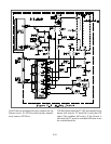
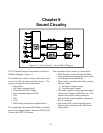
Figure 8-2 illustrates the Overall Sound Circuitry
Block Diagram. The AV/SW ICs, IC2L00 and
IC2K00, used to select Main and Sub Picture Video/
Color are also used to the select the Sound sources.
IC2L00 selects Main and Sub sound sources from
the Main Tuner (decoded by MCS circuitry in
IC3A01), Sub Tuner, External NTSC Inputs 1-3 and
from Component Inputs 1 and 2. The selected sig-
nals are directed to IC2K00.
IC2K00 selects the signals from either IC2L00, DVI,
DTV, VGA Inputs or the DM Module.
The Sub (PIP) sound signal is routed from IC2K00
to the PIP Sound Output Jacks. The selected main
Sound signal is directed to Audio Control circuitry,
also in IC3A01. The sound signal from IC3A01 is
amplified in IC3E01 and directed to the speakers.
The input signals to IC3A01 are also directed to the
Monitor Output Jacks. Only fixed level sound is
available at the Monitor Output Jacks.
Digital Audio Output
There is one additional audio output signal in the
V23 chassis, External Digital Audio Output on the
rear of the DM. This is an AC-3 digital data stream
(when available from a digital source). It allows con-
nection to an external A/V Receiver with an AC-3
Decoder. If the signal has been fully encoded, the
AC-3 Decoder is capable of producing 5.1 surround
sound, 5 full audio channels (20 kHz) and one low
frequency enhancement channel (120 Hz).


