


3
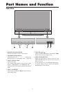
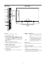
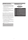
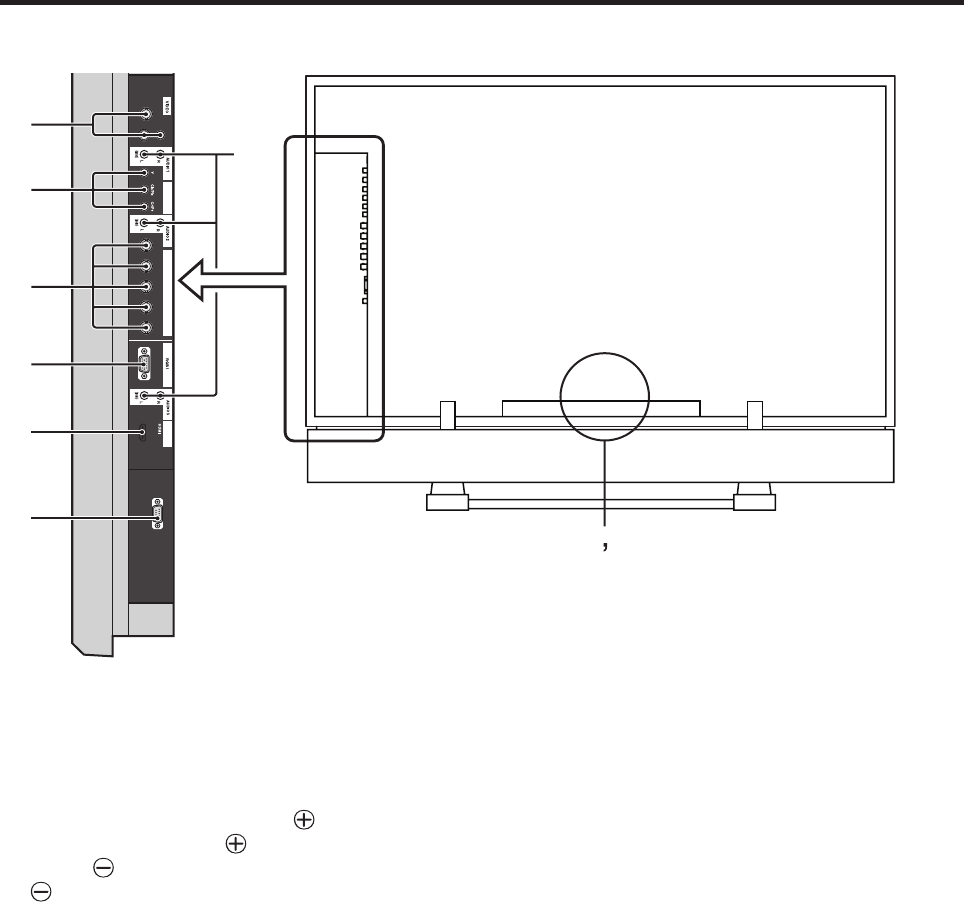
Side View Rear View
A AC IN
Connect the included power cord here.
B EXT SPEAKER L and R
Maintain the correct polarity. The (positive) speaker
wire is connected to the EXT SPEAKER terminal
and the (negative) speaker wire is connected to the
EXT SPEAKER terminal on both LEFT and
RIGHT channels.
C INPUT1, 2, 3 (BNC, RCA, S-Video)
Connect VCR’s, DVD’s or Video Cameras, etc. here.
D AUDIO1, AUDIO2, AUDIO3
These are audio input terminals.
The input is selectable. Select which video input to
assign them to from the audio menu screen.
E COMPONENT1
Connect DVD’s, Cable Boxes or High Definition
sources, etc. here.
F RGB2 / COMPONENT2
COMP2: You can connect DVDs, High
Definition sources, Cable Boxes, etc.
here.
This input can be set for use with an
RGB or component source. (see page
23, Setting the BNC connectors.)
RGB2: You can connect an analog RGB signal
and the syncronization signal.
G RGB1 (D-Sub)
Connect an analog RGB signal from a computer, etc.
here.
H MONITORLINK/HDMI
Connect a digital signal from a source with a HDMI
output.
I MONITORLINK CONTROL (RS-232C)
This terminal is used when operating and controlling
the display externally (by external control).
AB
D
C
E
F
G
H
I
INPUT 3
MONITORLINK
CONTROL
INPUT 1
INPUT 2
MONITORLINK
R/Cr/Pr G/Y
B/Cb/Pb H V
COMPONENT 1
RGB2/COMPONENT2