


21
21
Part II: Installation
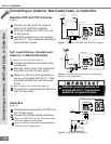
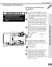
Connecting a DTV Receiver
Connecting a DTV Receiver
DTV Receiver with RGB Video
Connections
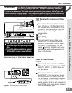
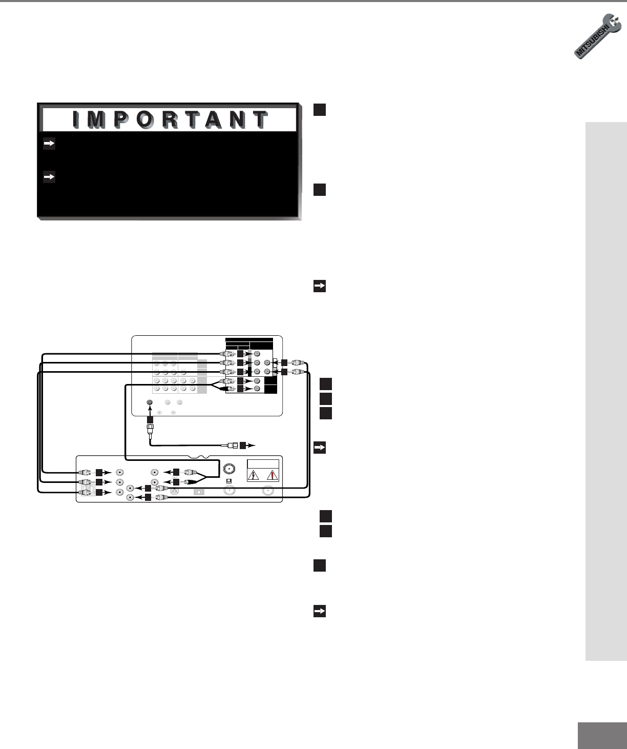
(Figure 1)
1
Connect the outside antenna, cable, or
satellite to ANT, or SATELLITE IN on the
DTV receiver (see your DTV receiver’s
owner’s guide for instructions, and cable
compatibility).
2
Connect the incoming terrestrial antenna,
or cable (not satellite) to ANT-A on the
TV back panel (a coaxial splitter, avail-
able at most electronic supply stores,
may be required to complete this instal-
lation).
Connect the RGB cables from the DTV
receiver to the TV back panel as listed
below (if your DTV receiver uses BNC-
type cables, use the adaptors shown in
gure 1, page 20):
DTV Receiver TV Back Panel
3
G (green) = Y
4
R (red) = Pr
5
B (blue) = Pb
If the DTV receiver has outputs for H
and V sync, connect as listed below
(DO NOT connect if DTV receiver uses
“Sync on Green”):
6
H (horizontal sync) = H
7
V (vertical sync) = V
8
Connect the L (left) and R (right) audio
cables from the DTV receiver and to
DTV AUDIO on the TV back panel.
To utilize the benets of a digital A/V
receiver, connect your DTV receiver’s
digital audio out to a digital input on your
digital A/V receiver.
Figure 1. Connecting the DTV receiver with RGB video
connections.
Y
G
Pb
B
Pr
R
V
H
HIGH RESOLUTION INPUT
INPUT
3 PIP
S-VIDEO
COMPONENT
480i /480p
1 (YPrPb)
2 (YPrPb)
DTV (YPrPb/GRBHV)
480i /480p /1080i
VIDEO
MONITOR
ACTIVE A/V
NETWORK
IR - HOME
THEATER
21
OUTPUT
AUDIO-
LEFT/
(MONO)
AUDIO-
RIGHT
AUDIO-
LEFT/
(MONO)
AUDIO-
RIGHT
ANT-BLOOP OUTANT-A
AUDIO
L
R
H
V
G
R
B
S-VIDEO
VCR
CONTROL
DIGITAL
AUDIO OUT
PHONE JACK
RF
REMOTE
SATELLITE IN
IN FROM ANT
OUT TO TV
CH 3
CH 4
CAUTION
RISK OF ELECTRICAL SHOCK
DO NOT OPEN
White
Red
4
3
5
6
7
6
7
8
8
8
8
3
4
5
TV back panel
2
Incoming Antenna,
or Cable.
2
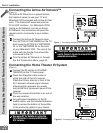
See Appendix B, page 65, for RGB video
signal compatibility information.
For digital audio connections, see your
DTV receiver and A/V receiver Owner’s
Guides.