


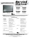


MODELS: WD-52627 / 52628 / 62627 / 62628 / 62827 / 62927 / 73727 / 73827 / 73927
Page 3
INTRODUCTION ................................................................................................................................5
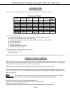
Model Dimensions and Weight Specifiations ................................................................................... 5
PRODUCT SAFETY NOTICE ............................................................................................................. 5
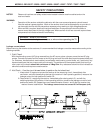
SAFETY PRECAUTIONS ................................................................................................................. 6
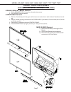
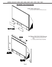
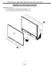
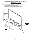
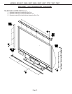
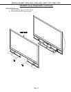
DISASSEMBLY ................................................................................................................................. 7
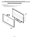
Front Disassembly (WD-52627 / WD-52628 / WD-62627 / WD-62628............................................. 7
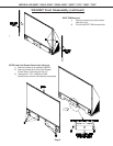
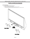
Front Disassembly (WD-62827) ...................................................................................................... 8
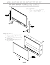
Front DisassembLY (WD-62927) ................................................................................................... 11
Front Disassembly (WD-73727 / WD-73827)................................................................................. 15
Front Disassembly (WD-73927) ....................................................................................................17
Rear Disassembly ........................................................................................................................ 19
Chassis Disassembly & Accessing PWBs ................................................................................... 20
Out of Cabinet Chassis Operation ................................................................................................. 26
Optical Engine Replacement ......................................................................................................... 29
DIAMOND SHIELD
TM
Removal ........................................................................................................ 34
SERVICING THE LENTICULAR LENS AND FRESNEL SCREEN ..................................................... 35
Removal of the Lenticular Screen and Fresnel Lens ...................................................................... 35
Installation of the Lenticular Screen and Fresnel Lens ................................................................... 36
ADJUSTMENTS ............................................................................................................................... 37
Option Menu & Defaults ................................................................................................................ 37
LED Indicator Diagnostics ............................................................................................................. 38
Error Codes Operational Check ..................................................................................................... 39
Remote Operational Mode ............................................................................................................ 40
Service Adjustment Mode ............................................................................................................. 40
Service Adjustment Mode Operation .................................................................................... 40
Resetting Data to factory values and Transferring data ......................................................... 41
Optical Engine Adjustment............................................................................................................ 42
Test Signal activation ........................................................................................................... 42
Preliminary .......................................................................................................................... 42
Locking Screw ..................................................................................................................... 42
Trapezodial Distortion Adjustment ........................................................................................ 43
Rotation Adjustment.............................................................................................................43
Hortizontal & Vertical Position.............................................................................................. 44
USING LEAD FREE SOLDER .......................................................................................................... 45
CHIP PARTS REPLACEMENT ......................................................................................................... 46
REPLACEMENT PARTS .................................................................................................................. 47
Parts Ordering .............................................................................................................................. 47
Critical and Warranty Parts Designation........................................................................................ 47
Parts Tolerance Codes .................................................................................................................. 47
Quick Reference List .................................................................................................................... 48
SERVICE PARTS LIST .................................................................................................................... 49
SCREEN ASSEMBLY PARTS LIST.................................................................................................. 60
WD-52627 / WD-52628 / WD-62627 / WD-62628 .......................................................................... 60
WD-62827 / WD-62927 ................................................................................................................. 71
WD-73727 / WD-73827 / WD-73927 ............................................................................................. 62
CONTENTS