


MODELS: WD-52627 / 52628 / 62627 / 62628 / 62827 / 62927 / 73727 / 73827 / 73927
Page 43
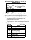
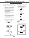
ADJUSTMENT PROCEDURES
Adjustment Locations
The Mechanical Adjustements are accessed
though the opening for the Card Reader.
Locations of the Adjustmentts ar shown In
Figure 3.
CAUTION: Do Not force an adjust-
ment past the end of it’s range,
UNIT-ADJUSTER damage may
result.
[A-1]
[B-1]
[A-3]
[A-2]
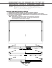
Figure 4: Adjustment
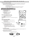
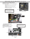
Locking Screws and Wedge Removal
Before mechanical adjustments can be made, locking screw [B-1]
and [B-2] must be loosened.
• [B-1] is located on the front of the UNIT-ADJUSTER.
(Figure 1)
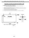
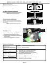
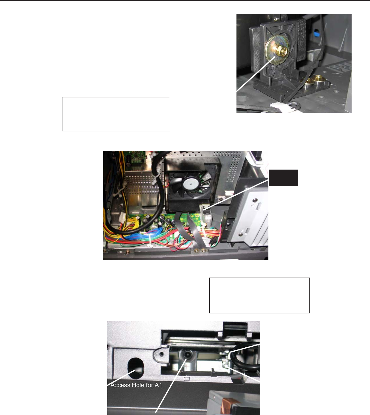
• [B-2] is accessible from the rear of the unit on the
right side of the Optical Engine (from the rear).
(Figure 2)
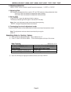
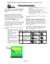
• Remove the rubber wedge shown in Figure 3. (52
inch and 62 inch models Only)
[B-2]
Figure 2: Side Locking Screw
Figure 3: Rubber Wedge (52 and 62 inch models only)
WEDGE
WARNING: DO NOT loosen [B-2] too
far. The nut on the other side may drop
off. Then the Optical Engine must be
removed to re-install the nut.