20
21
Connecting MonitorLink™, NetCommand® IR Emitter
Other A/V Device
1
Ferrite
Core
A/V Receiver
D IG IT AL
SU R R O U N D
S
CH
2
or
IR EMITTER
R
NetCommand IR
REPEATER
use with
NetCommand
controlled devices
use with
non-NetCommand
controlled devices
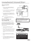
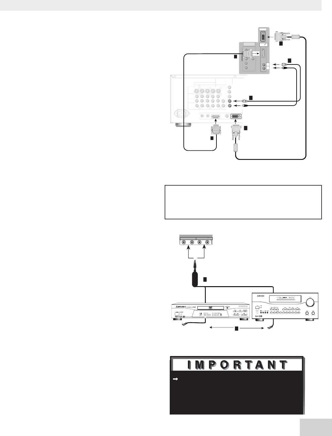
Figure 14. Connecting MonitorLink
Figure 15. Connecting IR Emitters
WS-48413, WS-55413, WS-65413
MonitorLink/DVI
(Figure 14)
1. Connect a MonitorLink/DVI cable from the
TV back panel to the Mitsubishi HD Receiver/
Controller back panel.
2. Connect the MonitorLink Control/RS-232 cable
from the TV back panel to the Mitsubishi HD
Receiver/Controller back panel.
3. Connect the L (left) and R (right) audio cables
from the HDTV receiver to AUDIO LEFT and
AUDIO RIGHT on the MonitorLink section of
the TV back panel.
NOTE: The 29 pin MonitorLink/DVI and
RS-232 cables can be found at your local
electronics store.
IR Emitter Repeater and
NetCommand® IR
(Figure 15) (WS-, WS-, WS-)
The two IR jacks labeled REPEATER are not used by
NetCommand, but will repeat any IR command received
by the TV. The NetCommand® IR jacks are used by
NetCommand to control external devices. They both
connect the same way:
1. Connect one of the IR emitters to one IR
EMITTER jacks on the TV back panel.
2. Place the IR emitter cable under or on top of each
A/V device. Place the IR lens directly in front of
the A/V device infrared signal receiver, usually
located behind the front translucent panel of the
receiver.
3. If you are connecting to only one A/V device,
place the unused transmitter in an out-of-the-way
location.
4. For permanent installation of the IR emtter cable,
use the included double sided adhesive tape to
secure the body of the emitter to the A/V receiver,
DVD player, Cable box, etc...
Note: The TV back panel and connections shown here are for reference only and may vary by model.
AUDIO-
LEFT/
(MONO)
AUDIO-
RIGHT
WS-48413, WS-55413, WS-65413
back panel
403XF-5K
1
1
2
2
OUTPUTS
TO
DISPLAY
1
2
3 4
MONITOR
PIP
INPUT
TO
AVRECEIVER
A
C
I
N
DIGITALAUDIO
OUTPUT
MonitorLink
TM
/DVI
MonitorLink
TM
CONTROL/RS-232
IROUTPUT
NetCommand
R
S-VIDEO
VIDEO
AUDIO
LEFT
AUDIO
RIGHT
White
Red
Mitsubishi HD-5000
receiver/controller back panel
3
White
Red
3
ferrite
core
ferrite
core
Y
G
Pb
B
Pr
R
V
H
DTV(YPbPr/GBRHV)
480i/480P/1080i
MONITORLINK
TM
/DVI
MONITORLINK
TM
CONTROL
RS-232C
403XF-5K
Do not use the IR emitter connections with
devices that can receive the remote control
signal directly, as the signals can interfere with
each other.
CAUTION: To assure continued FCC compliance,
the user must use a shielded video interface cable with
bonded ferrite cores at both ends, when using the
MonitorLink/DVI input.


