


— 4 — — 5 — — 6 —
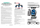
Connecting 2-wire RS-485 Serial Devices
RS-485
Rx
Tx Rx
Tx
RS-485
GND
Data-
Data+
GND
D-
D+
TCF-142
TCF-142
Serial
Device
Serial
Device
D-
GND
D+
Data-
GND
Data+
Copper CopperFiber
Connecting RS-232 Serial Devices
PC
Tx
Rx
GND
Copper CopperFiber
RS-232
Rx
Tx Rx
Tx
GND
Rx
Tx
RS-232
Tx
GND
CTS
RTS
DSR
DTR
Rx
Tx
Rx
CTS
RTS
DSR
DTR
GND
TCF-142
TCF-142
Serial
Device
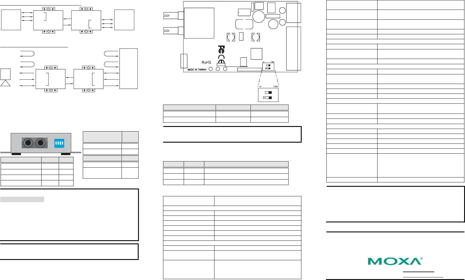
6. Switch Settings
There are 4 DIP switches on the top end of the TCF-142. SW1 and SW2
are used to set the serial interface. SW3 is used to enable or disable the
120 Ω termination resistor. SW4 is used to enable “Ring” mode or enable
“Point to Point” mode.
ON
123
4
Serial Connection SW1 SW2
RS-232 ON OFF
RS-422 OFF OFF
RS-485 4-wire OFF OFF
RS-485 2-wire OFF ON
Built-in 120 Ω
Terminator
SW3
Enable ON
Disable OFF
SW4
Ring mode ON
Point to Point
mode
OFF
ATTENTION
For Fiber Ring Users:
To avoid problems when setting up a fiber ring, each TCF-142 unit
making up the ring must be powered down and set to “Ring mode.” Next,
make sure all cables are connected properly, and then power up all
devices connected to the ring. After
powering up the TCF-142 units, if
the Rx LEDs of the converters glow continuously, power down and then
power up ONE of the TCF-142 units in the ring to return the network to
normal operation.
NOTE “Ring Mode” can only be sued for half-duplex applications
(e.g., RS-485 multi-drop communication).
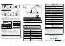
The DIP switch array called DIP-2 is located inside the TCF-142. DIP-2
has two DIP switches used to adjust the pull high/low resisters.
NOTE: SW1 and SW2 should be set both to ON, or both to OFF.
Pull High/Low Resister DIP-2 SW1 DIP-2 SW2
150K (default) OFF OFF
1K ON ON
NOTE When termination is enabled, we recommend using the 1K
(ON/ON) setting.
7. LED Description
There are 3 LEDs on the front panel of the TCF-142.
LED Color Function
PWR Red Steady ON: Power is ON
Fiber Tx Green Blinking when fiber is transmitting data
Fiber Rx Orange Blinking when fiber is receiving data
8. Specifications
Model Name TCF-142-S, TCF-142-S-T,
TCF-142-M, TCF-142-M-T
Serial Communication
Signals for RS-232 TxD, RxD, SGND
Signals for RS-422 TxD+, TxD-, RxD+, RxD-, SGND
Signals for 4-wire RS-485 TxD+, TxD-, RxD+, RxD-, SGND
Signals for 2-wire RS-485 Data+, Data-, SGND
Baudrate 300 bps to 921.6 Kbps
Surge protection 15 KV ESD
Fiber Communication
Connector type ST
Distance TCF-142-S: Single mode fiber for 40 km
TCF-142-M: Multi mode fiber for 5 km
Support Cable TCF-142-S:
8.3/125, 8.7/125, 9/125 or 10/125 μm
TCF-142-M:
50/125, 62.5/125, or 100/140 μm
Wavelength TCF-142-S: 1310 nm
TCF-142-M: 850 nm
TX Output TCF-142-S: > -5 dBm
TCF-142-M: > -5 dBm
RX Sensitivity TCF-142-S: -25 dBm
TCF-142-M: -20 dBm
Point-to-Point Transmission Half or Full duplex
Multi-drop Transmission Half duplex, fiber ring
Environmental
Operating Temperature
0 to 60°C (32 to 142°F), 5 to 95 % RH
Extended Operating
Temperature (for -T models)
-40 to 75°C (-40 to 167°F)
Storage Temperature
-20 to 85°C (-4 to 185°F), 5 to 95 % RH
Power
Input Power Voltage 12 to 48 VDC *
Power Line Protection 1 KV Burst (EFT), EN61000-4-4
1 KV Surge, EN61000-4-5
Reverse Power Protection Protects against V+/V- reversal
Over Current Protection Protects against 2 signals shorted together: 1.1A
Power Consumption 100 mA at 12 VDC
Mechanical
Dimensions (W × D × H) 67 × 100 × 22 mm
90 × 100 × 22 mm (including ears)
Material Aluminum (1 mm)
Gross Weight 140g
Regulatory Approvals
CE Class B
FCC Part 15 sub Class B
TÜV EN 60950
UL UL 60950
EMI EN55022 1998, Class B
EMS EN61000-4-2 (ESD), Criteria A, Level 2
EN61000-4-3 (RS), Criteria A, Level 2
EN61000-4-4 (EFT), Criteria A, Level 2
EN61000-4-5 (Surge), Criteria A, Level 3
EN61000-4-6 (CS), Criteria A, Level 2
Free fall IEC 60068-2-32
WARNING
1. This unit is not meant to be sold to consumers. It will only be shipped
to manufacturers or factories.
2. The DC source should come from an external adapter or 12 to 48 VDC
source (not from DC mains) by using a transfer device.
3. This unit should be installed or set up by a qualified service person.
Copyright © 2006
Moxa Technologies Co., Ltd.
All rights reserved.
Reproduction without permission is prohibited.
Tel: +886-2-8919-1230
www.moxa.com
Fax: +886-2-8919-1231
support@moxa.com