


P33/24 HHM-HHMR — PARTS MANUAL — REV. #0 (03/10/06) — PAGE 2
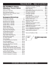
P33/24 HHM-HHMR — TABLE OF CONTENTS
Componet Drawings
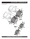
Standard Drum Assembly ...................................... 6-7
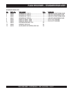
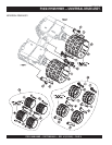
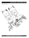
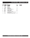
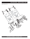
Universal Drum Assembly ...................................... 8-9
Smooth Drum 24” Assembly .............................. 10-11
Smooth Drum 33” Assembly .............................. 12-13
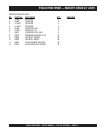
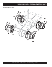
Hydraulic Motor 1 Assembly .............................. 14-15
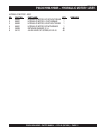
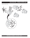
Hydraulic Motor 2 Assembly .............................. 16-17
Vibrator Assembly .............................................. 18-19
Vibrator Motor Assembly ................................... 20-21
Mounting Frame Assembly ................................ 22-23
Engine Cover Plate Assembly ............................ 24-25
Insulating Board Assembly ................................ 26-27
Cyclone Filter Assembly..................................... 28-29
Diesel Engine Assembly..................................... 30-31
Engine Shock Mount Assembly ......................... 32-33
Exhaust Silencer Assembly ................................ 34-35
Air Cleaner Assembly ......................................... 36-37
Pump Assembly ................................................. 38-39
Air Intake/Oil Drain Hose Assembly ................... 40-41
Fuel Lines Assembly .......................................... 42-43
Console Cockpit Assembly ................................ 44-45
Emergency Stop Bumper Assembly .................. 46-47
Valves Assembly ................................................ 48-49
Manual Operation Valves Assembly .................. 50-51
Remote Control Operation Valves Assembly ..... 52-53
Valve Block (Var. Excentric Weight) Assembly ... 54-55
Throttle Cable Assembly .................................... 56-57
Receiver/Console Assembly .............................. 58-59
Console Components 1 Assembly ..................... 60-61
Console Components 2 Assembly ..................... 62-63
Specification and part number
are subject to change without
notice.
NOTE
MQ RAMMAX P33/24
Vibratory Trench Roller
Table Of Contents ..................................................... 2
Here's How To Get Help ............................................ 3
Parts Ordering Procedures ....................................... 3
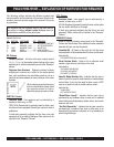
Explanation Of Code In Remarks Column ................ 4
Suggested Spare Parts ............................................. 5
Transmitter Control Box 1 Assembly .................. 64-65
Transmitter Control Box 2 ................................. 66-67
Battery Assembly ............................................... 68-69
Optional Battery Disconnecting Switch Assy ..... 70-71
Suction Filter Assembly...................................... 72-73
Dozer Blade Assembly ....................................... 74-75
Lift Cylinder Assembly........................................ 76-77
Valves Assembly ................................................ 78-79
HHM-HHMR Hydraulic Schematic ...........................80
HHMR-BD Hydraulic Schematic...............................81
Hydraulic Hose Layout ....................................... 82-83
Hydraulic Hose Locator Chart .................................84
Component Locator .................................................85
HHM Electrical Component Locator ........................86
HHM Wiring Schematic ............................................87
HHMR Electrical Component Locator ......................88
HHMR Wiring Schematic ..........................................89
Var. Exc. Weight Electrical Component Locator .......90
Var. Exc. Weight Wiring Schematic ...........................91
HHMR-BD Wiring Schematic ....................................92
Terms and Conditions of Sale ..................................94