


English-8
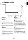
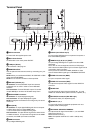
Terminal Panel
In
L/R
(IN2)
R
(IN3)
R, Cr/Pr
(IN)
G, Y, VIDEO
(IN)
B, Cb/Pb
(IN)
H
(IN)
V
(IN)
R
L
(IN3)Out
Out Out In Out L
L/R
(IN1)
InIn
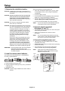
³ AC IN connector
Connects with the supplied power cord.
· Main Power Switch
On/Off switch to turn main power ON/OFF.
» LAN port (RJ-45)
LAN connection. See page 31.
¿ REMOTE IN/OUT
Use the optional wired remote control by connecting it to your
monitor.
NOTE: When you use Remote IN/OUT, IR CONTROL in OSD
menu should be NORMAL.
NOTE: Do not use this connector unless specifi ed.
´ RS-232C (D-Sub 9 pin)
IN connector: Connect RS-232C input from external
equipment such as a PC in order to control RS-232C
functions.
OUT connector: Connect RS-232C output. To connect
multiple MultiSync monitors via RS-232C daisy Chain.
² DISPLAYPORT connector
IN connector: To input DisplayPort signals.
OUT connector: To output DisplayPort signals.
NOTE: DisplayPort connectors are for image only. No sound
comes out.
¶ DVI (DVI-D)
IN connector: To input digital RGB signals from a computer
or HDTV device having a digital RGB output.
* This connector does not support analog input.
OUT connector: To output the DVI signal from either DVI IN
or HDMI connection. To output the DVI signal from the HDMI
connection, the HDMI input must be selected.
º HDMI connector
To input digital HDMI signals.
¾ VGA IN (mini D-Sub 15 pin)
To input analog RGB signals from a personal computer or
from other RGB equipment.
µ RGB/HV IN [R, G, B, H, V] (BNC)*
To input analog RGB signals or signals from other RGB
equipment.
This is also to connect equipment such as a DVD player,
HDTV device and Set-Top-Box. Sync-on-Green signal can be
connected to the G connector.
This input can be used with an RGB, DVD/HD or Video
source. Please select signal type in TERMINAL SETTING.
¸ VIDEO1 IN connector (BNC)*
To input a composite video signal.
¹ VIDEO OUT connector (BNC)
To output the composite video signal from the VIDEO IN
connector.
Ƹ AUDIO OUT
To output the audio signal from the AUDIO IN 1, 2, 3 and
HDMI to an external device (stereo receiver, amplifi er, etc.).
ƹ S-VIDEO IN connector (Mini DIN 4 pin)
To input the S-video (Y/C separate signal).
ƺ AUDIO IN 1, 2, 3
To input audio signal from external equipment such as a
computer, VCR or DVD player.
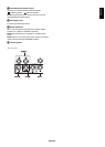
ƻ EXTERNAL SPEAKER TERMINAL
To output the audio signal from AUDIO 1, 2, 3 and HDMI.
Red terminal is plus (+).
Black terminal is minus (-).
Note: This speaker terminal is for 15W + 15W (8 ohm)
speaker.