


Po-32
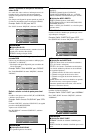
Definição de Vídeo-wall
Utilize esta caraterística para configurar o vídeo-wall 4-
25.
No menu “OPÇÃO3”, selecione “VÍDEO-WALL”, e
depois pressione o botão MENU/ENTER.
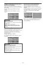
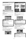
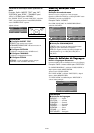
É apresentada a tela “VÍDEO-WALL”.
SEL. ADJ. VOLTAR
VÍDEO-WALL
DIVISOR
POSIÇÃO
MODO ÉCRAN
AUTO ID
AJUSTE IMAG.
ATRASO START
LIGAÇÃO PLE
REPT. TEMP.
: DESLIG.
: DIVIDIR
: DESLIG.
: DESLIG.
: DESLIG.
: DESLIG.
EXIT
Nota:
Deve ser utilizado um método de contingência
para desligar a energia em caso de emergência, durante
a configuração de vídeo-wall.
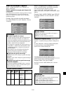
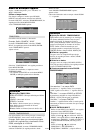
DIVISOR
Definir o vídeo-wall 4-25.
Exemplo: Definir “4”
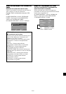
Em “DIVISOR” do menu de “VÍDEO-WALL”, selecione
“4”.
SEL. ADJ. VOLTAR
VÍDEO-WALL
DIVISOR
POSIÇÃO
MODO ÉCRAN
AUTO ID
AJUSTE IMAG.
ATRASO START
LIGAÇÃO PLE
REPT. TEMP.
: 4
: DIVIDIR
: DESLIG.
: DESLIG.
: DESLIG.
: DESLIG.
EXIT
Informação
Ⅵ Definições de DIVISOR
DESLIG., 1: 1 tela (função visualizar matriz não
funciona)
4: 4 telas (2ן2 video-wall)
9: 9 telas (3ן3 video-wall)
16: 16 telas (4ן4 video-wall)
25: 25 telas (5ן5 video-wall)
* Quando selecionar 4-25, defina a POSIÇÃO VÍDEO-
WALL.
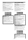
POSIÇÃO VÍDEO-WALL
Definir a posição para cada visor.
Exemplo: Definir “4”
No menu “VÍDEO-WALL”, selecione “POSIÇÃO”, e
depois pressione o botão MENU/ENTER.
É apresentada a tela “POSIÇÃO VÍDEO-WALL”.
Selecione “NÚM. 4” em “POSIÇÃO NÚM”.
ADJ. VOLTAR
POSIÇÃO VÍDEO-WALL
POSIÇÃO NÚM. 4
EXIT
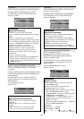
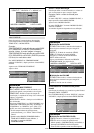
MODO ÉCRAN
Selecione o modo tela entre duas opções (Dividir,
Limpar).
Exemplo: Definir “BRANCO”
No “MODO ÉCRAN” do menu de “VÍDEO-WALL”,
selecione “BRANCO”.
SEL. ADJ. VOLTAR
VÍDEO-WALL
DIVISOR
POSIÇÃO
MODO ÉCRAN
AUTO ID
AJUSTE IMAG.
ATRASO START
LIGAÇÃO PLE
REPT. TEMP.
: 1
: BRANCO
: DESLIG.
: DESLIG.
: DESLIG.
: DESLIG.
EXIT
Informação
Ⅵ Definições MODO ÉCRAN
DIVIDIR: Combina telas alargadas e cria telas
múltiplas.
BRANCO: Corrigir o erro de alinhamento de partes
de telas combinadas e criar múltiplas telas.
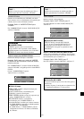
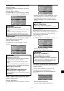
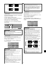
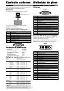
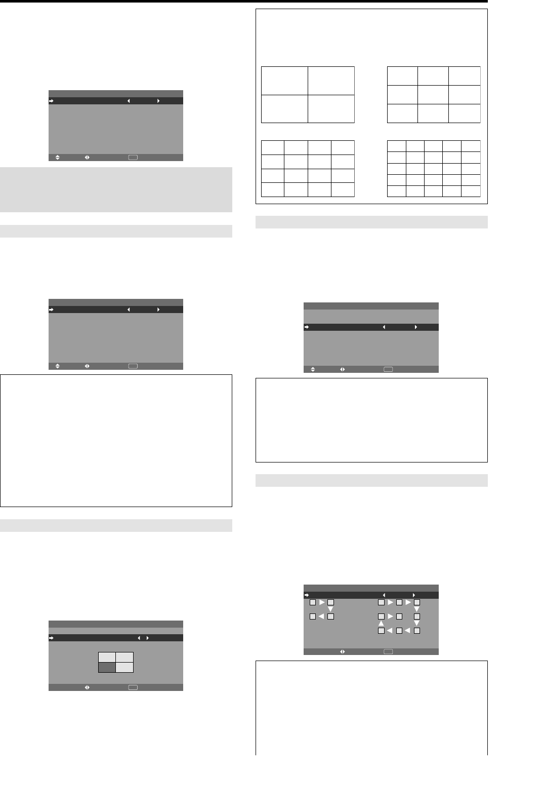
Informação
Ⅵ Definições de POSIÇÃO DE VÍDEO-WALL.
1 tela: Não é necessário definir POSIÇÃO.
4 tela 9 telas
16 telas 25 telas
NO. 1
NO. 2
NO. 4
NO. 3
NO. 7
NO. 8
NO. 9
NO. 10
NO. 11
NO. 12
NO. 13
NO. 14
NO. 15
NO. 16 NO. 17 NO. 18 NO. 19
NO. 20 NO. 21 NO. 22 NO. 23
NO. 24 NO. 25 NO. 26 NO. 27
NO. 28 NO. 29 NO. 30 NO. 31
NO. 32 NO. 33 NO. 34 NO. 35 NO. 36
NO. 37 NO. 38 NO. 39 NO. 40 NO. 41
NO. 42 NO. 43 NO. 44 NO. 45 NO.46
NO. 47 NO. 48 NO. 49 NO. 50 NO. 51
NO. 52 NO. 53 NO. 54 NO. 55 NO. 56
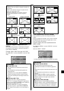
AUTO ID
Esta caraterística define automaticamente os números
ID de múltiplos visores ligados entre si.
Exemplo: Definir “LIGADO”
Definir o número ID para o visor Nº. 1 no menu
NÚMERO ID.
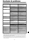
Em “AUTO ID” no menu “VÍDEO-WALL”, selecione
“LIGADO”, e depois pressione o botão MENU/ENTER.
CABOS
ORDEM DE CONEXÃO
ADJ. VOLTAR
AUTO ID
AUTO ID : LIGADO
EXIT
1
2
8
9
3
4
6
5
7
1
2
4
3
Informação
Ⅵ Definições AUTO ID
LIGADO: Ativa as funções AUTO ID. No caso
apresentado abaixo, o visor 1 será definido como ID
1, visor 2 como ID2, etc.
Esta ação só pode ser definida quando o vídeo-wall
2ן2 ou 3ן3 está selecionado.