


5
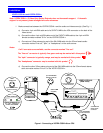
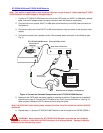
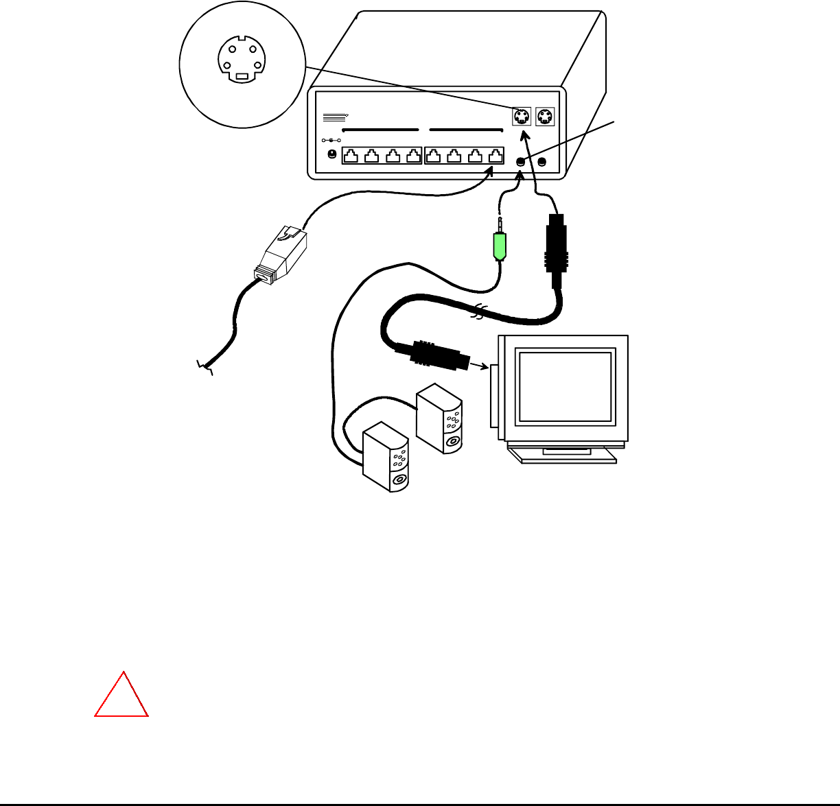
2. Connect the local user to the VOPEX-C5SVA-x (see Fig. 2)
a. Connect one end of another SVEXT-xx-MM cable to the 4-pin miniDIN female connector
marked "S-Vout" on the VOPEX-C5SVA-x.
b. Connect the other end of the SVEXT-xx-MM cable to the 4-pin miniDIN female connector on the
local s-video display.
c. Connect the cable from the local speakers into the 3.5mm stereo audio connector marked "Line
Out" on the VOPEX-C5SVA-x.
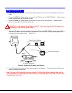
Figure 2- Connect Local User components and CAT5 cable to VOPEX-C5SVA-8
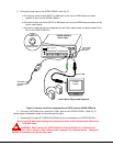
3. Connect a CAT5 cable to any one of the “Cat5x” ports on the VOPEX-C5SVA-x. (See Fig. 2.)
When properly inserted the cable end should snap into place.
4. Repeat step 3 for each ST-C5SVA-R-600 Receiver to be connected to the VOPEX-C5SVA-x.
Note: If an RJ45 wall outlet is being used, connect the other end of the extension cable to the
RJ45 wall outlet.
WARNING: Never connect the VOPEX-C5SVA-x Extender/Splitter to an ethernet card,
ethernet router, hub or switch or other ethernet RJ45 connector of an ethernet device. Damage to
devices connected to the ethernet may result.
!
S-Video
Display
CAT5 Cable to
ST-C5SVA-R-600
Receiver
Local User's Display and Speakers
5VDC
2A
-
+
87
6
54321
Line
Out
Line
In
Cat5
NTI
NET WORK
TEC HNOLO GIES
INCO RPOR ATED
Tel: 330- 562- 7070
Fax :330- 562- 1999
1275 Dan ne r Dr
Aurora , OH 44202
www.n ti 1.com
R
VOPEX-C5SVA-8
(Rear View)
3.5mm Female
Stereo Audio
Connector
S-Vin
S-Vout
4-pin miniDIN Female
S-Video Connector
VIDEO
CONNECTOR
SVEXT-xx-MM