I
NFRARED
M
AIN
S
YSTEM
U
NIT
STEP
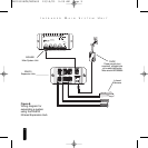
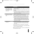
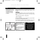
4. Plug the flashers into the
flasher outputs. If you need
to extend the wire, use
a 2-conductor 16 gauge
or larger (See “Tech Tip”
on Page 6).
DESCRIPTION
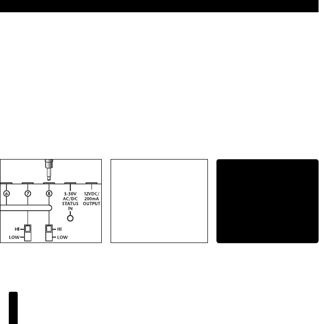
Route the connecting wire to the IR Main System Unit. Connect
the 3.5mm plug into the jack labeled “Flasher Output” on the
MSU480.
WARNING!
Before connecting flashers to ports 7 & 8 set the HI/LOW switch-
es to the appropriate position. Depending on the flashers being
used:
1. MF1, MF2, MF1VF, MF2VF – LOW position.
2. IRB1 – HI position.
MF Series MicroFlashers may be damaged by excessive flasher
level output from the Main System Unit!
Do not connect any flashers to the 12VD/200mA output at any
time. If 12VDC is applied to the flashers they will be damaged.
11
BE SURE TO OBSERVE
PROPER POLARITY WHEN
EXTENDING THE FLASHER
WIRE.
The wire lead marked with
a gray stripe is positive (+);
the unmarked lead is
negative (-).
“TECH TIP”
Make all final connections
to the MSU before
connecting the power
supply. This will avoid
potential damage
to components.
DS00330ACN/MSU480 12/19/03 9:05 AM Page 11


