


11
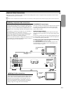
Optional Video Connections
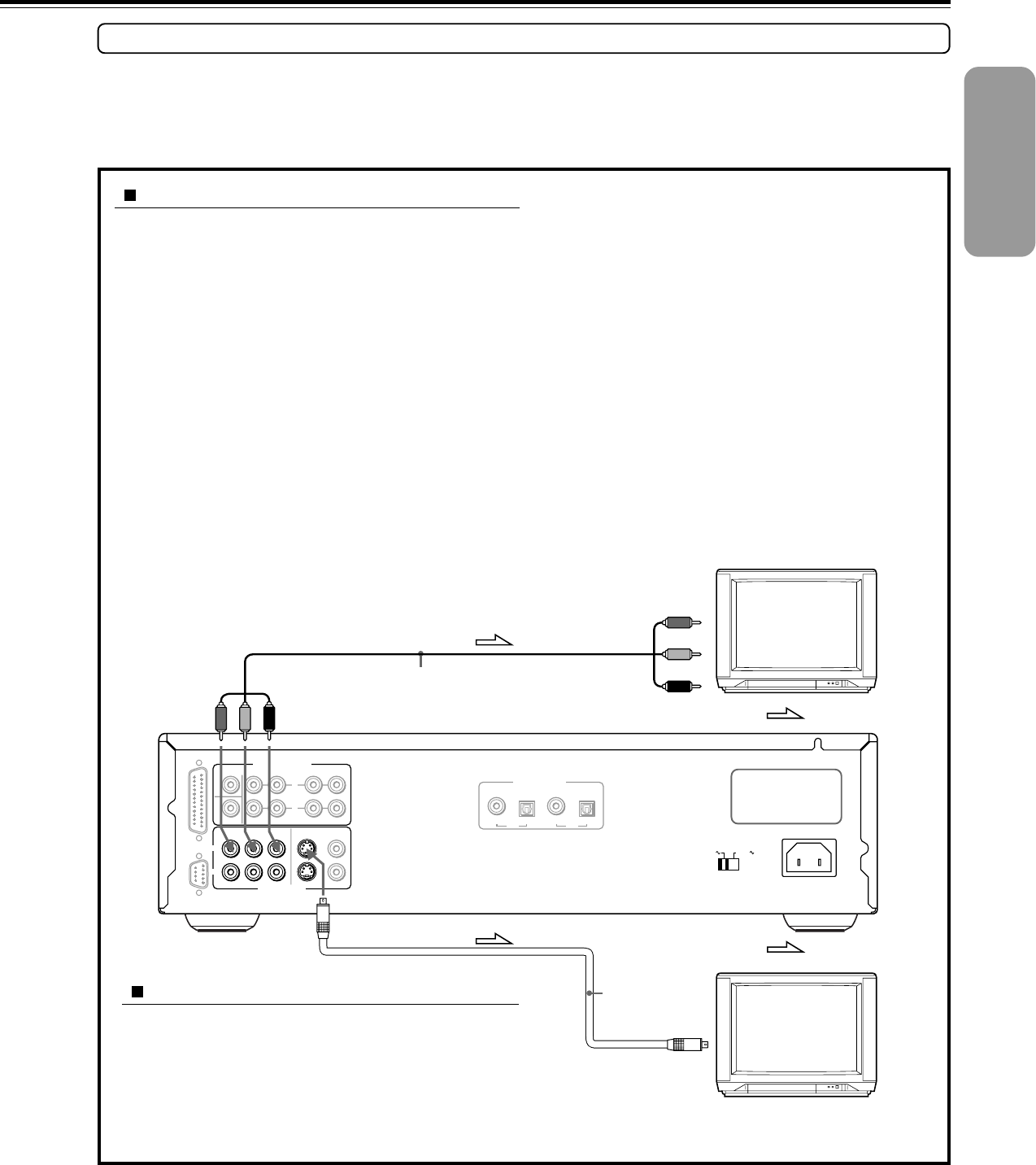
Visible improvements in DVD-Video quality can be achieved by making either S-video or component video connections to a TV or monitor
compatible with these types of connections.
Note
When either S-video or component video connection is made, it is not necessary to make composite video connections using the yellow cord of the audio-video
cable.
Making S-video connections
If the TV or monitor has an S-video input, making this type of
video connection will produce improved picture quality. Using an
S-video cable, connect the VIDEO OUTPUT S VIDEO CH1 or
CH2 jack to the corresponding S-video input jack on the TV.
Be sure to set Audio Out Select to “Analog 2Ch” using the on-
screen menu explained in “Customizing the Function Settings”
starting on page 44. See page 48 for direct information.
Making component video connections
If the TV or monitor has component video inputs, making this type
of video connection will produce the ideal picture quality for the
presentation of DVD-Video. Using a componect video cable (sold
separately), connect the VIDEO OUTPUT COMPONENT CH1 or
CH2 jacks to the corresponding component video input jacks on the
TV.
Actual labels for component video inputs may vary depending on
the TV manufacturer. (e.g. Y, R-Y, B-Y or Y, C
B, CR)
In some TVs or monitors, the color levels of the playback picture
may be reduced slightly or the tint may change. In such a case,
adjust the TV or monitor for optimum performance.
Be sure to set Audio Out Select to “Analog 2Ch” using the on-screen
menu explained in “Customizing the Function Settings” starting on
page 44. See page 48 for direct information.
S-video cable
(supplied)
To S-video
input
Component video cable
(not supplied)
To component video
inputs
: Signal flow
: Signal flow
Y
PB
PR
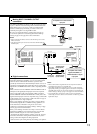
DO NOT connect the
power cord until all
connections are
complete.
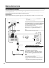
PROGRESSIVE outputs/inputs
Some TVs or monitors are equipped with component video inputs that
are capable of reproducing a progressively scanned video signal.
Connecting to these inputs allows you to view the highest quality
pictures with less flicker.
Interlaced outputs/inputs
Some TVs or monitors are equipped with component video inputs.
Connecting to these inputs allows you to enjoy higher quality picture
playback.
In some TVs or monitors, the color levels of the playback picture may
be reduced slightly or the tint may change. In such a case, adjust the
TV or monitor for optimum performance.
To switch the output signal (Progressive/Interlaced)
Press PROGRESSIVE on the remote control.
The output signal alternates between component progressive and
component interlaced. For details, refer to “Selecting Progressive
Scan Video Output” on page 42.
VIDEOS VIDEO
VIDEO
OUTPUT
COAXIAL
COAXIAL
OPTICAL
OPTICAL
CENTER
SURR FRONT CH
1CH
2
SUBWOOFER
COMPONENT
YP
B PR
RS 232 MULTI CHANNEL OUTPUT
ANALOG
OUTPUT
DIGITAL
OUTPUT
CH
1
CH
2
R
L
CH 1
CH 2
AC INLET
120
V
VOLTAGE SELECTOR
220
-230
V