


7 DIN-191 & DIN-192 USERS MANUAL
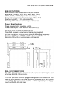
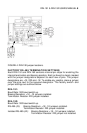
Figure 2. RS-485 biasing & termination resistors.
RS-485 TERMINATION & BIASING SETTINGS
Proper termination and biasing of any RS-485 based system can be
performed by properly enabling the correct resistors inside each DIN-191
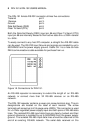
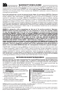
or DIN-192. Figures 3.0 and 4.0 show the location of the jumpers on the
printed circuit board. The jumpers are shown in their factory set locations
to enable the selected resistors. Insert or remove the jumpers as required
to properly terminate any RS-485 system.
Figure 3. DIN-192 jumper locations.