


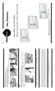

Step 1
Install hex screw into pads on bottom of back post. (Fig. 1a)
Install cable port covers into back post. (Fig. 1b)
Fig. 1a
Fig. 1b
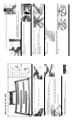
Step 2
Lay main frame face down on floor.
Match holes on support legs to holes on main frame support brackets.
Loosely secure support legs to main frame using hex head screws and supplied hex
wrench. (Fig. 2a)
Secure back post to support using long hex head bolts and sup-
plied hex wrench. (Fig. 2b) Tighten all support leg screws.
Stand table upright.
Fig. 2a
Fig. 2b
Fig. 3a
Step 3
Determine desired height of middle shelf.
Install Phillips head screw and shelf pad into rear shelf support bracket. (Fig. 3a)
Models: G343, G343T, G348
Secure rear shelf support bracket to back post with countersunk hex screws. (Fig. 3b)
Secure side shelf support brackets to main frame with
Phillips head screws. (Fig. 3c)
Note: Slide bracket fully to the outside edge of frame. (Fig. 3d)
Fig. 3b
Fig. 3c Fig. 3d
Step 4
Install end caps into foot sections on front of base frame and side of back
frame. (Figs. 4a & 4b)
Step 5
Place adhesive rubber pads on support legs and main frame.
(Figs. 5a & 5b)
Rock the stand to check that it is level and stable.
Note: For unstable condition, un-screw shortest leveling foot
until table sits level.
Step 6
Identify glass shelves. (Fig. 6a)
Slide bottom shelf onto lower frame members. (Fig. 6b)
Rotate bottom shelf into position on lower frame mem-
bers. (Fig. 6c)
Fig. 4a Fig. 4b
Fig. 5a
Fig. 5b
Fig. 6a
Fig. 6b Fig. 6c