


20
Connecting the DV-SP502/DV-SP502E—Continued
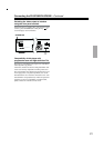
• Connect the DV-SP502/DV-SP502E to the TV
directly. If you connect the DV-SP502/DV-SP502E to
a VCR, TV/VCR combination, or video selector, the
playback picture may be distorted as DVD videos are
copy protected.
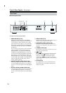
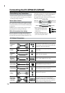
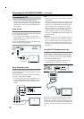
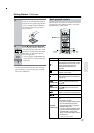
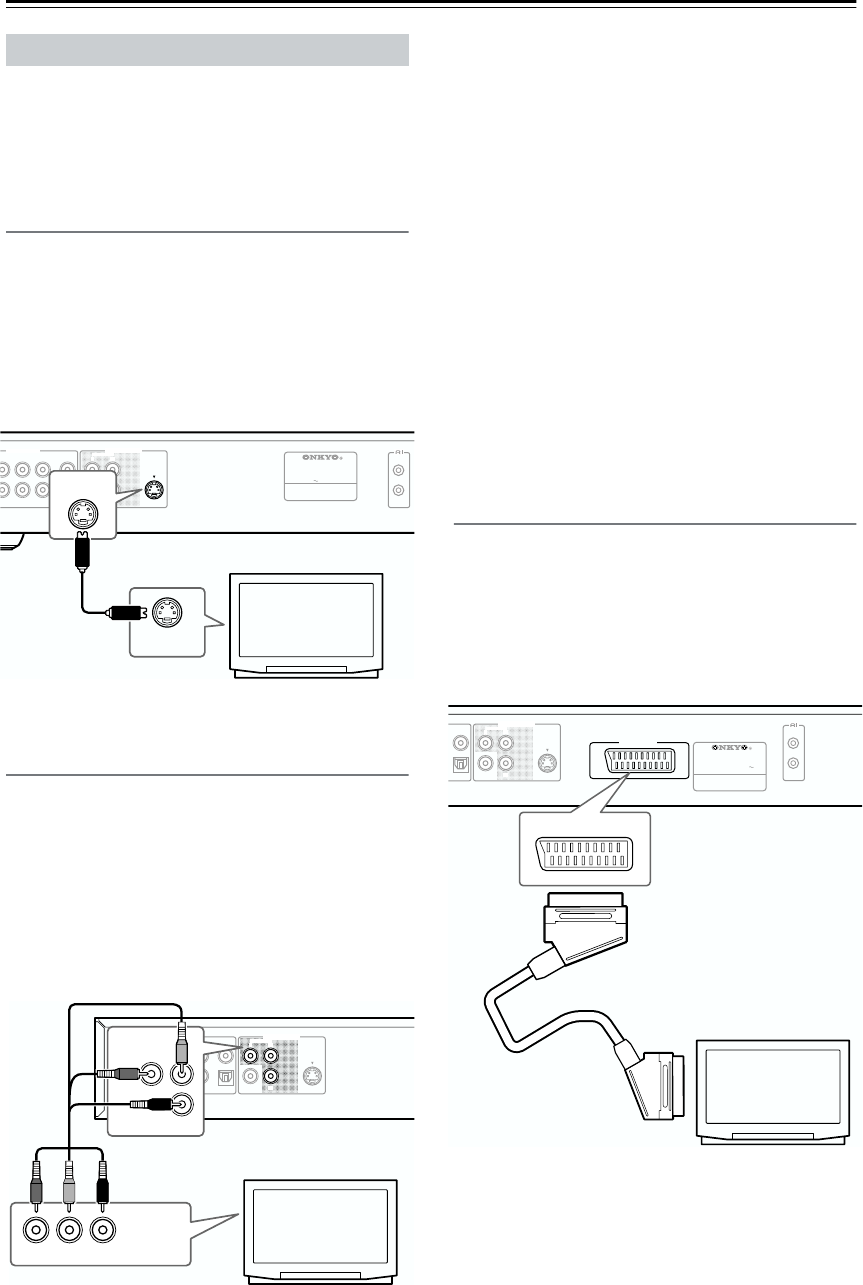
Using S Video
If your TV (or other equipment) has an S Video input,
you can use this instead of the standard (composite) out-
put for a better quality picture.
• Use an S Video cable (supplied) to connect the S
VIDEO OUTPUT to an S Video input on your TV (or
monitor or AV receiver).
Line up the small triangle above the jack with the same
mark on the plug before plugging in.
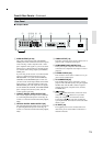
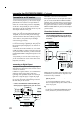
Using Component Video
You can use the component video output instead of the
standard video out jack to connect this player to your TV
(or other equipment).
This should give you the best quality picture from the
three types of video output available.
• Use a component video cable (not supplied) to con-
nect the COMPONENT VIDEO OUTPUT jacks to a
component video input on your TV, monitor or AV
receiver.
Note:
• Watching progressive scan video from the component
video outputs
This player can output progressive scan video from the
component video output. Compared to interlace video,
progressive scan video effectively doubles the scan-
ning rate of the picture, resulting in a very stable,
flicker-free image. To set up the player for use with a
progressive scan TV, see Video Output settings on
page 46. When the player is set to output progressive
scan video, the PROGRESSIVE indicator lights in the
front panel display.
Important:
• If you connect a TV that is not compatible with a pro-
gressive scan signal and switch the player to progres-
sive, you will not be able to see any picture at all. In
this case, switch everything off and reconnect using
the supplied video cable, then switch back to Interlace
(see page 21).
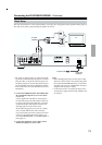
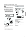
Using SCART (European model only)
If your TV has a SCART-type AV input, you can use a
SCART cable to connect this player to your TV. This
type of connection carries both the sound and the picture,
so there’s no need to connect up the AUDIO OUTPUT
L/R and VIDEO OUTPUT jacks.
• Use a SCART cable (supplied) to connect the AV
CONNECTOR to an AV input on your TV.
This connector can output composite video, S Video, or
RGB video. The default setting is composite, which
should work with all TVs. Consult the manual that came
with your TV to see if you can use one of the higher qual-
ity settings. See page 46 for how to change the video out-
put.
Connecting Your TV
REMOTE
CONTROL
SUPER AUDIO CD & DVD AUDIO/
VIDEO PLAYER
MODEL NO. DV
-
SP
502
RATING
:
AC 120V 60Hz 11W
VIDEO
S VIDEO
SURR CENTER
2
M
IX
AUDIO OUTPUT
DIGITAL
SUB
WOOFER
OPTICAL
COAXIAL
PB
Y
P
R
COMPONENT
VIDEO OUTPUT
S VIDEO IN
S VIDEO
TV
VIDEO
S VIDEO
R
L
SURR CENTER
12
FRONT/D. MIX
AUDIO OUTPUT
DIGITAL
SUB
WOOFER
OPTICAL
COAXIAL
PB
Y
P
R
COMPONENT
VIDEO OUTPUT
PB
COMPONENT
Y
Y
PB PR
COMPONENT
VIDEO IN
PR
TV
VIDEO
S VIDEO
DIGITAL
OPTICAL
COAXIAL
PB
Y
P
R
COMPONENT
VIDEO OUTPUT
SUPER AUDIO CD & DVD AUDIO/
VIDEO PLAYER
MODEL NO. DV
-
SP
502E
RATING
:
AC 100
-
240V
50/ 60Hz 12W
REMOTE
CONTROL
AV CONNECTOR
SCART
AV CONNECTOR
TV