


17
OPTICAL COAXIAL
L
R
L
R
SURR
11
+
2
SUB
WOOFER
AC
INLET
AV
CONNECTOR 2
REMOTE
CONTROL
DIGITAL OUTPUT
S VIDEO VIDEO
Y
P
B
P
R
COMPONENT
CH 1 CH 2 FRONT SURR 1 CENTER SURR 2
MODEL NO.
DV
-
SP
800
SACD
&
DVD
AUDIO/VIDEO PLAYER
AV CONNECTOR
1
OUT
IN/
OUT
VIDEO
OUTPUT
ANALOG
OUTPUT
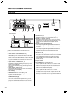
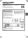
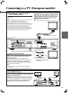
■ Connecting to a TV Using the SCART
Cable (European models)
Connect the DVD Player and your TV using the supplied
SCART cable.
Note
S Video and RGB signals are not output from AC CONNECTOR 1.
If the TV is compatible with S video signals
After completing the steps on page 20, set [Video Out] to
[S Video] using the menu explained in “Adjusting Audio and Video
Settings” starting from page 46. See page 53 for direct information.
If an RGB monitor is connected to the DVD Player
After completing the steps on page 20, set [Video Out] to [RGB]
using the menu explained in “Adjusting Audio and Video Settings”
starting from page 46. See page 53 for direct information.
OPTICAL COAXIAL
L
R
L
R
SURR
11
+
2
SUB
WOOFER
AC
INLET
AV
CONNECTOR 2
REMOTE
CONTROL
DIGITAL OUTPUT
S VIDEO VIDEO
Y
P
B
P
R
COMPONENT
CH 1 CH 2 FRONT SURR 1 CENTER SURR 2
MODEL NO. DV
-
SP
800
SACD
&
DVD
AUDIO/VIDEO PLAYER
AV CONNECTOR
1
OUT
IN/
OUT
VIDEO
OUTPUT
ANALOG
OUTPUT
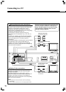
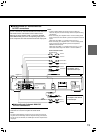
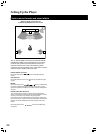
Connecting to a TV (European models)
: Signal flow
Be sure to set the TV Aspect after connection using
the Setup Navigator explained in “Setting Up the
Player” starting on page 21 or the function setting
menu explained in “Adjusting Audio and Video
Settings” starting on page 46.
DO NOT connect
the mains lead at
this time.
Stereo audio connection cable
To audio input
Making S-video connections
If the TV or monitor has an S video input, make the S video
connection. The S video connection will provide higher
quality picture playback.
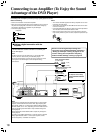
By making connections to a stereo system, you can
improve the quality of the sound. Using an audio cable (not
supplied), make audio connections from the ANALOG
OUTPUT CH 1 or CH 2 L and R jacks to the corresponding
jacks on the stereo component.
Notes
• If you make the S video connection, leave the yellow plug
disconnected.
• If the TV audio is monaural, leave the red plug disconnected.
S video connection cable
To S video input
L (White)
R (Red)
SCART cable
To AV CONNECTOR input terminal
TV/
Monitor
Audio/video
component
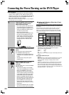
AV CONNECTOR 1 jack
When the unit is in standby mode, audio and video (RGB, S, and
composite) input to AV CONNECTOR 1 SCART jack will be
output from AV CONNECTOR 2.
For instance, if an audio/video component is connected to AV
CONNECTOR 1 with a SCART cable, and a TV or monitor is
connected to AV CONNECTOR 2, audio and video input from
the component will be output to AV CONNECTOR 2 and
displayed on the TV or monitor during standby mode.
: Signal flow