


–
14
–
EN
1L25
DVD/VCR VCR
AUDI O OUTAUDIO IN
VIDEO OUTVIDEO IN
S-VIDEO
OUT
COMPONENT
VIDEO OUT
AUDIO
OUT
DVD
Y
Cb L
Cr R
L
ANT-IN
ANT-OUT
R
L
R
DIGITAL
AUDIO OUT
COAXIAL
OPTICAL
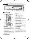
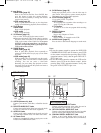
A/V-compatible
or
wide screen TV
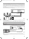
To COMPONENT VIDEO INPUT jacks To COMPONENT VIDEO OUT jacks
To Right (red) and Left (white)
AUDIO INPUT jacks
To Right (red) and Left (white)
AUDIO OUTPUT jacks
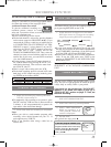
FOR TVs WITH
COMPONENT VIDEO IN JACKS
Use a component video cable (commercially available) in place of the yellow DVD/VCR video cable and S-VIDEO jack to
enjoy higher quality pictures.
The component video connection only supplies video (picture) in the DVD mode of the DVD/VCR COMBINATION UNIT.
Therefore, in order to use the VCR features or view TV channels at the DVD/VCR COMBINATION UNIT, you still need
to either connect the RF coaxial cable between the ANT-OUT jack of the DVD/VCR COMBINATION UNIT and the TV’s
Antenna In jack, or connect the yellow VCR video cable as described earlier (Fig. 1). To connect the supplied RF cable, see
page 13.
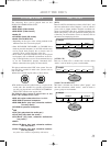
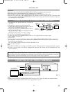
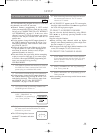
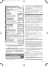
CONNECTING TO A STEREO AMPLIFIER EQUIPPED WITH DIGI-
TAL INPUT JACKS SUCH AS MD DECK OR DAT DECK
Use an audio coaxial digital cable or an audio optical cable (commercially available) for the audio connections.
Connecting to an amplifier equipped with digital input jacks such as MD Deck or DAT Deck.
¡If you use the OPTICAL jack, remove the protective cap.
DVD/VCR VCR
AUDIO OUTAUDIO IN
VIDEO OUTVIDEO IN
S-VIDEO
OUT
COMPONENT
VIDEO OUT
AUDIO
OUT
DVD
Y
Cb L
Cr R
L
ANT-IN
ANT-OUT
R
L
R
DIGITAL
AUDIO OUT
COAXIAL
OPTICAL
To COAXIAL DIGITAL
AUDIO INPUT jack
To COAXIAL DIGITAL
AUDIO OUT jack
(Stereo Receiver)
Amplifier equipped with digital
input jacks, MD deck,
DAT deck, etc.
To OPTICAL DIGITAL AUDIO OUT INPUT jack
To OPTICAL DIGITAL
AUDIO OUT jack
Notes
¡The audio source on a disc in the 5.1 channel Dolby Digital surround format cannot be recorded as digital
sound by an MD or DAT deck.
¡
Set DOLBY DIGITAL to OFF for audio output in the setup mode. Playing a DVD disc using incorrect settings may gen-
erate noise distortion, and may also damage the speakers. (See page 29 to set DOLBY DIGITAL to OFF.)
[Fig. 4]
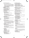
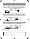
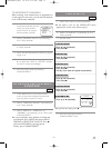
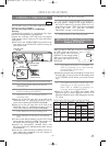
FOR TVs WITH S-VIDEO INPUT JACK
Use an S-Video cable (commercially available) in place of the yellow video cable to enjoy higher quality pictures.
The S-Video connection only supplies video (picture) in the DVD mode of the DVD/VCR COMBINATION UNIT.
Therefore, in order to use the VCR features or view TV channels on the DVD/VCR COMBINATION UNIT, you still
need to either connect the RF cable between the ANT-OUT jack of the DVD/VCR COMBINATION UNIT and the
TV’s Antenna In jack, or connect the yellow video cable as described earlier (Fig.1). To connect the supplied RF cable,
see page 13.
CONNECTING TO A TV THAT HAS AN S-VIDEO INPUT JACK OR
COMPONENT VIDEO IN JACKS
DVD/VCR VCR
AUDIO OUTAUDIO IN
VIDEO OUTVIDEO IN
S-VIDEO
OUT
COMPONENT
VIDEO OUT
AUDIO
OUT
DVD
Y
Cb L
Cr R
L
ANT-IN
ANT-OUT
R
L
R
DIGITAL
AUDIO OUT
COAXIAL
OPTICAL
To S-VIDEO OUT jackTo S-VIDEO INPUT jack
To Right (red) and Left (white)
To AUDIO OUT jacksTo AUDIO INPUT jacks
A/V-compatible or
wide screen TV
[Fig. 3]
[Fig. 2]
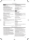
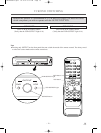
HINT FOR OPTICAL CABLE (COMMERCIALLY AVAILABLE)
• Optical cable may be damaged when bent at acute angles. Ensure cables are coiled in loops with a diam-
eter of 6inches (15cm) or more when storing them.
• Use a cable which is 9.8ft (3m) or shorter.
• Insert cable plugs firmly into the jacks when making connections.
• If a plug has minor scratches or is dirty, clean it with a soft cloth before inserting it into a jack.
• Replace the protective cap on the OPTICAL jack when it is not in use.
H9405UD2î≈.qx33 03.6.30 5:47 PM Page 14