


76
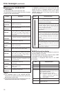
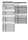
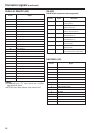
The VTR can be operated by commands when the RS-
232C interface is used.
(See command table on pages 79, 80.)
$ Conditions for acknowledging
commands from RS-232C interface
OThe REMOTE button on the front panel must be
set to the remote mode (REMOTE lamp ON).
OThe setup menu No. 204 “RS232C SEL” must be
ON.
If the above conditions are not met, [ACK] + [STX]
ER001 [EXT] is returned to the external unit.
Whether the [ACK] code is returned depends on the
setting which has been selected for setup menu
item No. 209 “RETURN ACK”.
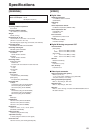
Hardware specifications
External interface specifications
RS-232C interface
OConnector specifications
Connector:
D-SUB 25-pin (crossover cable supported)
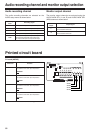
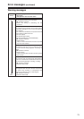
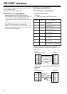
OExample of connection with controller (PC)
Using crossover cable with D-SUB 25-pin
connectors
Pin No. Signal Description
1 FG Protective ground
(Frame ground)
2 RXD Received data
(Data is sent to PC.)
3 TXD Transmitted data
(Data is received from PC.)
4 CTS Clear to send
(Shorted with pin 5.)
5 RTS Request to send
(Shorted with pin 4.)
6 DTR Data terminal ready
(No processing)
7 SG Signal ground
(Signal ground)
20 DSR Data set ready (+ voltage output
after communication enable status)
PC side
(D-SUB 25-pin connector)
VTR side
FG
TXD
RXD
RTS
CTS
DSR
SG
DTR
1
2
3
4
5
6
7
20
FG
RXD
TXD
CTS
RTS
DTR
SG
DSR
1
2
3
4
5
6
7
20
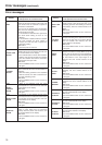
Using crossover cable with D-SUB 9-pin and 25-pin
connectors
PC side
(D-SUB 9-pin connector)
VTR side
RXD
TXD
DTR
SG
DSR
RTS
CTS
2
3
4
5
6
7
8
FG
RXD
TXD
CTS
RTS
DTR
SG
DSR
1
2
3
4
5
6
7
20