


6 z
OPTIONAL EQUIPMENT CONNECTIONS
ENGLISH
Optional Equipment Connections
Note:The remote control must be programmed with supplied
codes to operate the optional equipment.
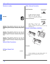
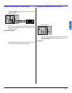
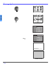
VCR Connection
VCRs, video disc players, video game equipment, and
DSS equipment can also be connected to the video inputs.
See the optional equipment manual for more information.
Note:VIDEO 1 input is a dual-purpose input. It is primarily
intended for connection with 480i devices such as a DVD
player using the Y P
B
P
R
component video jacks and
Audio L & R jacks. However, it can also be connected to
conventional composite video sources such as a VCR,
using only the Y/Video jack and Audio L & R jacks. The
on-screen label will display Component or Video 1
depending on which source is connected.
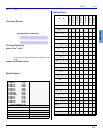
Note:Rear A/V jacks diagram may vary, depending on model.
Please refer to the FEATURE CHART on page 3 for your
model’s capabilities.
Procedure
• Connect equipment as shown to front or rear Audio/
Video input jacks.
• Select the Video mode by pressing TV/VIDEO button.
• Operate optional equipment as instructed in equipment
manual.
Note:Do not connect S-VIDEO and VIDEO signal to INPUT 2 at the
same time. If both are connected, signal interference will result.
Use either the S-VIDEO or the Video signal only (models CT-
20SL14, CT-24SL14, CT-27SC14 and CT-27SL14 only).
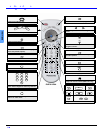
Front Control Panel
The front control panel can be used to access menus and
switch video mode when the remote control is not
available.
Procedure
• Connect equipment to front Audio/Video input jacks.
• Press TV/VIDEO button to select desired input mode.
• Operate optional equipment as instructed in equipment
manual.
Note:Front A/V jacks diagram may vary, depending on model.
Please refer to the FEATURE CHART on page 3 for your
model’s capabilities.
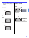
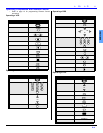
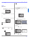
Cable Box Connection
Follow this diagram when connecting your television to a
Cable Box.
Procedure
• Tune the television to channel 3 or 4 depending on the
RF out setting of the cable box.
• Using the cable box, tune to the premium cable channel
you want to view.
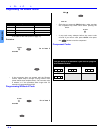
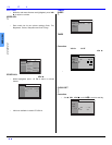
Digital TV - Set-Top Box (DTV-STB) or DVD
Player Connection
Use this diagram to connect the Panasonic DTV-STB
(Digital TV-Set-Top Box) to the back of your TV.
Note:Rear A/V jacks diagram may vary, depending on model.
Please refer to the FEATURE CHART on page 3 for your
model’s capabilities.
Notes:
• There are three video jacks, Y, P
B
, and P
R
.
Separate component color inputs provide
luminance and color separation. Use the L (left)
and R (right) audio inputs.
• Select DTV-STB to 480i output mode. TV set can
receive 480i signal only. Picture distortion will result
if any other type of format is selected (i.e. 480p,
720p or 1080i).
TERMINALS ON BACK OF TELEVISION
VCR
PLAY
STOP
R
E
W
FF