


OP_ONAL EQ_PMENT CONNEC_ONS
Optional Equipment Connections
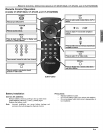
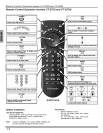
Note: The remote control must be programmed with supplied
codes to operate the optional equipment (EUR7613Z10
only).
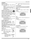
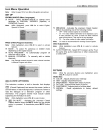
VCR Connection
VCRs, video disc players, video game equipment, and
DSS equipment can also be connected to the video inputs.
See the optional equipment manual for more information.
Note for models with Component video input:
VIDEO 1 input is a dual-purpose input. It is
primarily intended for connection with 480i devices
such as a DVD player using the Y PB PR
component video jacks and Audio L & R jacks.
However, it can also be connected to conventional
composite video sources such as a VCR, using
only the Y/Video jack and Audio L & R jacks. The
on-screen label will display Component or Video 1
depending on which source is connected.
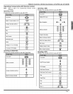
CONt_ECTFONSOn BACK OF THE TV
/
_NPUTI
R AUDIO L
.......... © ©
WDEOINPUTS
I_ p. YNIDEC
© © ©
INPUT 2
....... @ © ©
R aUDIO • VgEO
VIDEOOUT
,_U_lO OUT
N_T OUT ANTIN
® ®
Note: Rear A/V jacks diagram may vary, depending on model
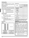
Please refer to the FEATURE CHART on page 2 for your
model's capabilities.
Procedure
Connect equipment as shown to rear Audio/Video input
jacks.
Select the Video mode by pressing TVNIDEO button.
Operate optional equipment as instructed in equipment
manual.
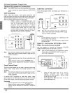
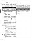
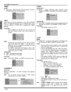
Front Control Panel
The front control panel can be used to access menus and
switch video mode when the remote control is not
available.
Note: Front A/V jacks diagram may va_ depending on model.
Please refer to the FEATURE CHART on page 2 foryour
model capabilities.
A second VCR, Camcorder, a video disc player, video
game equipment or DSS equipment can also be connected
to the vidoeo inputs. See the optional equipment manual.
Procedure
Connect equipment to front Audio/Video inputjacks.
Select the Video mode by pressing TVNIDEO button.
Operate optional equipment as instructed in equipment
manual.
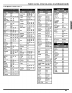
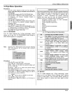
Cable Box Connection
Follow this diagram when connecting your television to a
Cable Box.
F
CONNECTIONS ON BACK OF THE TV
r
INPUT I
R--AUDIO --L
COMPONENT@@
VIDEO INPUTS
I_pR-- P -- YIVIDEO
© © ©
INPUT 2
voEo © © ©
R__AUDIO --L V_DEO
CABLES NOT SUPPLIED
Note: Rear A/V jacks diagram may va_ depending on
model. Please refer to the FEATURE CHART on page
2 for your model's capabilities.
Procedure
Tune the television to channel 3 or 4 depending on the
RF out setting of the cable box.
Using the cable box, tune to the premium cable channel
you want to view.
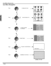
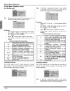
Digital TV - Set-Top Box (DTV-STB) or DVD
Player Connection (some models)
Use this diagram to connect the Panasonic DTV-STB
(Digital W-Set-Top Box) to the back of your TV.
Note: Rear A/V jacks diagram may vary, depending on model.
Please refer to the FEATURE CHART on page 2 for
your model's capabilities.
Notes:
There are three video jacks, Y, PB, and PR.
Separate component color inputs provide
luminance and color separation. Use the L (left)
and R (right) audio inputs.
Select DTV-STB to 480i output mode. TV set can
receive 480i signal only.
4o