


43
Setup menus
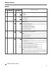
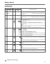
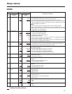
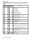
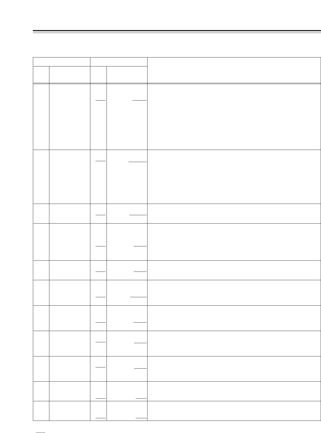
603 V-MUTE SEL
0000
0001
0002
0003
N MUTE
GRAY
BLACK
NOISE
For setting whether to mute the video output signal when a blank part of the tape is
detected during playback.
0: The video output signal is not muted. (It is frozen.)
1: The video output signal is muted and turned gray.
2: The video output signal is muted and turned black.
3: The video output signal is muted and turned into noise.
600 VIDEO IN SEL
0000
0001
0002
INTSG
HDSDI
1394
For selecting the video signals to be input.
0: The internal signal selected by VIDEO INT SG is generated.
1: The serial video signal supplied to the HD SDI IN connector is selected.
2: The compressed digital signals supplied to the DV connector are selected.
When this happens, the audio input signals will also be supplied from the DV
connector (digital video interface).
<Notes>
O This item’s setting cannot be changed while a tape is being played back.
O When 1394 is selected as this item’s setting, “1080i” is selected as the menu
item No.630 [1080i>HD_OUT] setting and “720p” is selected as the menu item
No.632 [720p>HD_OUT] setting.
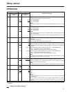
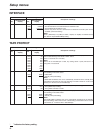
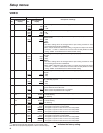
626 D/C ENH H
0000
0001
0dB
+1dB
For enhancing the horizontal outlines during down-conversion.
0: 0dB
1: +1dB
627 D/C ENH V
0000
0001
0dB
+1dB
For enhancing the vertical outlines during down-conversion.
0: 0dB
1: +1dB
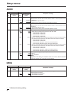
602 SDI IN MODE
0000
0001
DR OFF
DR ON
For selecting how to process the serial input.
0: The 8 higher bits whose two lower bits have been rounded off are recorded.
1: The dynamically rounded 8 higher bit signal is recorded.
604 FREEZE SEL
0000
0001
FIELD
FRAME
For selecting the freeze mode of the still pictures and the slow play mode.
0: Field freeze, field slow
1: Frame freeze, frame slow
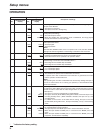
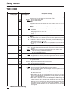
615 V OUT SEL
0000
0001
CMPNT
CMPST
For selecting what signals are to be output from the VIDEO OUT1 output
connector.
0: The HD component signals are output.
1: Composite signals are output.
616 OUT MATRIX
0000
0001
YPbPr
RGB
For selecting what signals are to be output from the HD component output
connector.
0: The YPBPR signals are output.
1: The RGB signals are output.
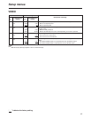
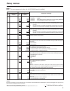
601 VIDEO INT SG
0000
0001
0002
0003
0004
0005
100%CB
75%CB
SMPTE
BLACK
PLL
EQ
For selecting the type of internal signal.
0: A 100% color bar signal is selected.
1: A 75% color bar signal is selected.
2: An SMPTE color bar signal is selected.
3: A black signal is selected.
4: The PLL signal is selected. (This signal is used for the adjustments performed
before the unit was shipped from the factory.)
5: The EQ signal is selected. (This signal is used for the adjustments performed
before the unit was shipped from the factory.)
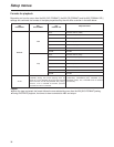
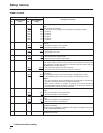
620 DOWNCON
MODE 0000
0001
0002
FIT_V
FIT_H
FIT_HV
For setting the image processing during down-conversion.
0: Side cut mode
1: Letter-box mode
2: Squeeze mode
621 UPCON V MODE
0000
0001
0002
FIT_V
FIT_H
FIT_HV
For setting the image processing during up-conversion.
0: Side panel mode
1: Top and bottom cut-off in vertical direction
2: Stretch mode
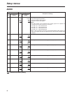
VIDEO
Item Setting
No.
Superimposed
display
No.
Superimposed
display
Description of settings
“
” indicates the factory setting.