


Do this adjustment after replacing a P.C.B.
Purpose: To maintain video signal output compatibility.
12 Electrical Adjustment
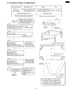
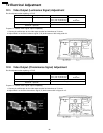
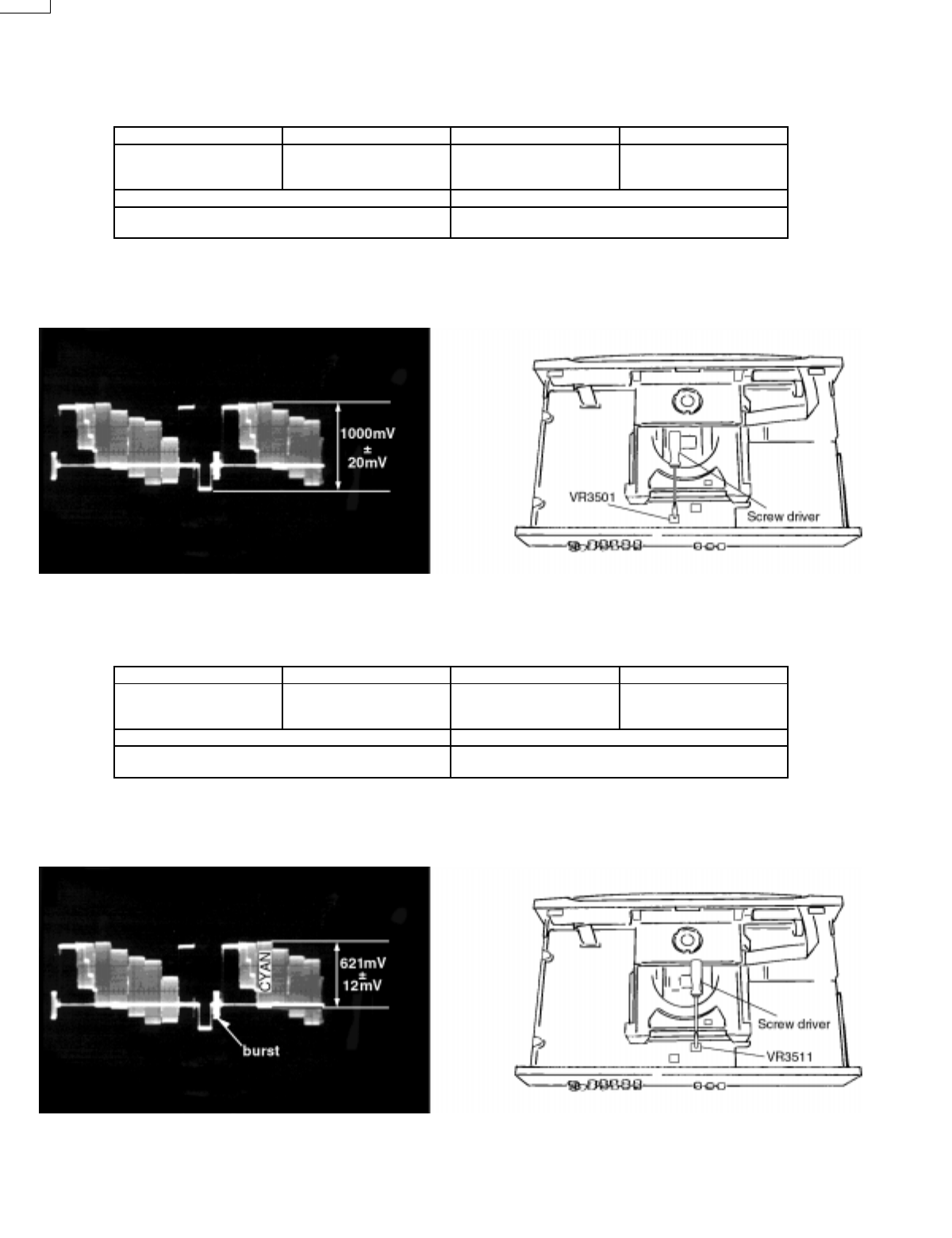
12.1. Video Output (Luminance Signal) Adjustment
Do this adjustment after replacing a P.C.B.
Measurement point Adjustment point Mode Disc
Video output terminal VR3501 (mother P.C.B.) Color bar 75%
PLAY (Title 46):DVDT-S15
PLAY (Title 12):DVDT-S01
DVDT-S15
or
DVDT-S01
Measuring equipment, tools Adjustment value
Screwdriver, Oscilloscope
200mV/div, 10µsec/div
1000mVp-p±20mV
Purpose: To maintain video signal output compatibility.
1. Connect the oscilloscope to the video output terminal and terminate at 75 ohms.
2. Adjust VR3501 so that the luminance signal (Y+S) level becomes 1000 mVp-p±20 mV.
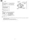
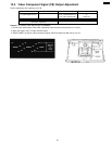
12.2. Video Output (Chrominance Signal) Adjustment
Measurement point Adjustment point Mode Disc
Video output terminal VR3511 (mother P.C.B.) Color bar 75%
PLAY (Title 46):DVDT-S15
PLAY (Title 12):DVDT-S01
DVDT-S15
or
DVDT-S01
Measuring equipment, tools Adjustment value
Screwdriver,Oscilloscope
200mV/div, 10µsec/div
621mVp-p±12mV
1. Connect the oscilloscope to the video output terminal and terminate at 75 ohms.
2. Adjust VR3511 so that the chrominance signal (C) level becomes 621 mVp-p±12 mV.
26
DVD-RV60