


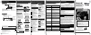

• Timer Recording • Location of Controls (Remote Control Buttons, Front View of the VCR)
Location of Controls
*Important: If a remote control button does not work when pressed,
press the VCR button on the remote and try the button again.
- 7 -
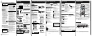
Timer Recording
1 1) Press PROG*.
2) Press
to display program screen.
Press PROG to end programming.
2
2) Set remaining items,
press
to select and
press
to set START/ STOP times, CH(channel) or
LINE input (p. 9 of “Advanced Operations” book), and
tape speed (p. 3).
1) Set record DATE,
press
to select:
1~31= one time,
or DAILY= MON~ FRI,
or WEEKLY= same time
each week and press
.
3
To Enter More Programs
Press
to select and
press
to set an unused program.
Then repeat step 2.
Or, press PROG to exit.
Timer Recording
Example
Today
Press to select
desired program.
4
Press POWER off to set the timer recording. (“TIMER” lights on Multi Function Display.)
(Recording is not in progress)
a 1) Press PROG.
2) Press
to select LIST.
b
c
To Replace program...
d Press PROG to end the programming.
• If you are using a Cable Box, VCR Timer Programming Channel (Step 2 above) must
be set to the Cable Box output channel and your Cable Box must be manually set to
the desired channel. The Cable Box must be left on.
• If a power interruption occurs while programming the timer, the timer program(s) may be
canceled. If “TIMER PROGRAMS WERE LOST DUE TO POWER INTERRUPTION” appears
on-screen, please re-enter the timer programs.
Important notes when using DSS receiver
• When recording programs via DSS receiver, DSS receiver must be left on.
• When recording programs via an antenna or cable, DSS receiver must be turned off.
Review, Replace, or Clear Program
1) Press to display.
2) Repeat Step 2
(above) to set new
programs.
Press ADD/DLT.
or
To Clear program...
Press POWER and then STOP within 10
seconds to cancel the Timer Recording.
(The TIMER indicator goes out on Multi
Function Display.)
Cancel a Timer Recording
(Recording is in progress)
- 6 -
Notes
DAILY
7
21
31
68 9
SELECT / Selection Order
WEEKLY
(SAT)
WEEKLY
(MON)
WEEKLY
(SUN)
TIMER PROG.
L
I
ST
C
AN
C
EL
:
A
DD
/
DLT
SELECT :
SET :
EXIT
: PROG
DT
STA
R
T
ST
O
P
CH
SPD
7 9
:
00
A
12
:
00
A
08
SP
8
10
:
00
P
12
:
00
P
02
SP
10
8
:
00
P
9
:
00
P
10
SP
S
U
9
:
00
P
10
:
00
P
L1
LP
TIMER
PROG.
LIST
SELECT START DATE
DATE START
ST
O
P
C
H
SP
T
OD
A
Y
7
SUN
9
:
00A
12
:
00A
08
SELECT
:
END
: PROG
SET:
TIMER PROG.
L
I
ST
DT
STA
R
T
ST
O
P
CH
SPD
13
2 : 00
P
3
:
20
P
0
2
SLP
--
--
:
--
--
:
--
--
--
--
--
:
--
--
:
--
--
--
--
--
:
--
--
:
--
--
--
C
AN
C
EL
:
A
DD
/
DLT
SELECT :
SET :
EXIT
: PROG
SELECT
:
END
: PROG
DATE START
ST
O
P
C
H
SLP
SET:
SELECT START DATE
T
OD
A
Y
13
SA
T
--:--
--:--
--
TIMER
PROG.
LIST
TIMER PROG.
L
I
ST
C
AN
C
EL
:
A
DD
/
DLT
SELECT :
SET :
EXIT
: PROG
DT
STA
R
T
ST
O
P
CH
SPD
--
--
:
--
--
:
--
--
--
8
10
:
00
P
12
:
00
P
02
SP
10
8
:
00
P
9
:
00
P
10
SP
S
U
9
:
00
P
10
:
00
P
L1
LP
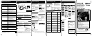
• Connections • Initial Setup • Clock Set • Select Channel • Playback • Record • Auto Operation
This video recorder, equipped with
HQ (High Quality) system, is
compatible with existing VHS
equipment. Only use tapes with the
mark. Only tapes tested and
inspected for use in 2, 4, 6, and 8
hour machines are recommended.
*Important: If a remote control button does not work when pressed,
press the VCR button on the remote and try the button again.
- 5 -
1
Insert a tape with a record tab (p. 3).
1 Insert a tape.
Special Features During Play
2 Press CH
or NUMBER keys
to
select the channel
.
• For “LINE” input, see p. 9 of “Advanced
Operations” book.
• If recording from a channel over 100, first
press 100 key then the other 2 digits.
3
Press SPEED
to select record speed (p. 3).
4
Press REC
to start recording.
• To edit, press PAUSE/SLOW to pause,
and again to resume recording.
5
Press STOP to stop recording.
2
Press PLAY to play tape.
• If tape has no rec. tab (p. 3), auto play begins.
One Touch Recording
(record in progress)
Press REC repeatedly to set length as follows:
30 min.
➛ 1 hr. ➛ 1:30 ➛ 2:00 ➛ 3:00
➛ 4:00 ➛ exit.
The VCR shuts off at the length set.
Record one station, watch another
Press VCR/TV
(“VCR” goes out on Multi Function Display),
➛ select channels on TV (recording continues).
Select channels on VCR (in STOP or
PAUSE mode)
Press VCR/TV
(“VCR” lights up on Multi Function Display),
➛ select channels on VCR.
Record on a Tape
Forward/Reverse Scene Search
➛ Press FF or REW.
➛ Press PLAY to release.
After search has begun, each additional
press of FF or REW changes speed as
shown below.
[SLP] : Approx. 21X
↔ Approx. 9X
[LP] : Approx. 9X
↔ Approx. 7X
[SP] : Approx. 7X
↔ Approx. 3X
If at 21X, 9X, or 7X speed the picture is
interrupted, change speed to 9X, 7X, or 3X.
Still (Freeze) Picture
➛ Press PAUSE/SLOW.
➛ Press PLAY to release.
Frame by Frame Picture
➛ Press PAUSE/SLOW in Still mode.
➛ Press PLAY to release.
Slow Motion Picture
➛ Hold down PAUSE/SLOW in Still mode.
➛ Press PLAY to release.
• Loose or peeling labels
may cause tape jam.
• These features work best in SP or SLP mode.
• The sound will be muted.
• To reduce picture noise, see “Manual
Tracking Control” on p. 3.
• After VCR is in Still or Slow mode 3 minutes, it
auto switches to Stop mode to protect the tape
and the video heads.
Press REW or FF in Stop mode to
Rewind or Fast Forward tape.
Press EJECT on remote,
or STOP/EJECT on VCR to eject tape.
3 Press STOP to stop tape.
Playback a Tape
• Watching one channel and recording
another is not possible when using Cable
Box or DSS Receiver.
• After 5 minutes in Pause mode, VCR stops
to protect the tape and the video heads.
• Picture interruption may occur with some TVs.
• FF and REW search speed may vary
depending on current tape position.
Notes
Playback / Record on a Tape
Auto Play
Insert a tape ➛ Power comes on ➛ Play starts if there is no record tab (see p. 3).
Auto Rewind
Play
Fast Forward
Play Auto Eject
(Repeat Play must be off)
Play ➛ Tape end ➛ Rewind ➛ Tape ejects if there is no record tab
Auto Operation Functions
Notes
Notes
➛ Tape end ➛ Rewind
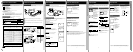
Connections / Initial Setup (Ready to Play)
Connecting
Connect cable from
Antenna/Cable to VCR’s IN
FROM ANT. jack.
Connect VCR’s OUT TO TV
jack to TV’s ANT. IN jack
with included RF Cable
accessory.
For ANT./Cable
➛➛
➛➛
➛
VCR
➛➛
➛➛
➛
TV
For DSS/Cable Box
➛➛
➛➛
➛
VCR
➛➛
➛➛
➛
TV
Connect your cable box’s
OUT jack to the VCR’s IN
FROM ANT. jack with an RF
cable.
Connect VCR’s OUT TO TV
jack to TV’s ANT. IN jack
with included RF Cable
accessory.
1
2
1
2
Please make all cable or antenna connections before plugging into the AC
outlet.
Plugging the VCR Power Cord into an AC wall outlet starts auto channel and clock set.
1 Turn TV on and tune to channel 3.
2 Plug VCR Power Cord into AC wall
outlet. VCR comes on and auto
channel and clock set starts.
WARNING
Over tightening “Nut type” RF coaxial cables
may damage jacks. Finger tighten only.
• If screen below does not appear, check
VCR - TV connection and, if TV is
tuned to channel 3, try switching it to
channel 4.
• To change VCR’s output channel,
please refer to “VCR’s Output Channel”
in Advanced Operations book (p. 12).
If you use a cable box, turn it on and set it
to the Public Broadcasting Station (PBS)
channel in your time zone. If you use a
DSS receiver, it must be turned off.
Initial Setup (Ready to Play)
VCR CLOCK CHANNEL
CH AUTO SET PROCEEDING
CANCEL :
STOP
3Settings are made automatically.
When setup is done, this screen
appears.
VCR CLOCK CHANNEL
9
/
29
/
20
0
2
SUN
2
:
20P
M
D
S
T
:
ON
SETT
I
N
G
: CH
10
AUTO CLOCK SET
C
O
M
PLETED
If “AUTO CLOCK SET IS INCOMPLETE”
appears, manually set clock.
See below.
AUTO CLOCK SET IS
INC
O
M
PLETE
PLEASE SET CLOCK BY
PRESSING ACTION KEY
VCR CLOCK CHANNEL
Manual Clock Set
If Auto Clock Set was incomplete.
1 Press ACTION* on remote to display
CLOCK menu.
VCR CLOCK CHANNEL
SELECT MONTH
DST:ON
1
/ /
:
SELECT :
SET :
EXIT
:
ACT
I
O
N
2 Press to select the month and
to set. In the same manner, select and
set the date, year, time, and DST
(Daylight Saving Time).
3 Press ACTION to start clock and exit.
- 4 -
Plugging the AC Power Plug into an AC outlet
VCR CLOCK CHANNEL
SET COMPLETED
DST:ON
9
/
29
/
20
0
2
SUN
2
:
20P
M
START
:
ACT
I
O
N
SET
:
IN FROM ANT.
TV
VCR
VHF/UHF
OUT
TO
TV
IN from
ANT./CABLE
1
2
IN FROM ANT.
TV
VCR
VHF/UHF
OUT
TO
TV
IN from
ANT./CABLE
Cable TV
Converter Box
1
2
Before Using
• Important Safeguards • Accessories • Head Cleaning • Loading Batteries • Prevent Tape Erasure • Specifications • Record/Playback Time
- 3 -
INSTALLATION
1 POWER SOURCE CAUTION
Operate only from a power source indicated on
the unit or in this manual. If necessary, have
your Electric Utility Service Company or Video
Products Dealer verify the power source in your
home.
2 POLARIZED OR GROUNDING PLUG
As a safety feature, this Video product comes
with either a polarized power cord plug (one
blade is wider than the other), or a three-wire
grounding type plug.
POLARIZED PLUG CAUTION:
This plug will only fit into an outlet one way. If you
cannot fully insert the plug, try reversing it. If it still
will not fit, have an electrician install the proper wall
outlet. Do not defeat the safety feature by tampering
with the plug.
GROUNDING PLUG CAUTION:
This plug will only fit into a three-hole grounding
outlet. If necessary, have an electrician install the
proper outlet. Do not defeat the safety feature by
tampering with the plug.
3 POWER CORD
Make sure power cords are routed so that they
are not likely to have anything rest on them, roll
over them, or be in the way of walking traffic.
If an extension cord is used, make sure it also
has either a polarized or grounded plug and that
the cords can be securely connected. Frayed
cords, damaged plugs, and damaged or cracked
wire insulation are hazardous and should be
replaced by a qualified service technician.
Overloaded outlets and extension cords are fire
hazards and should be avoided.
4 DO NOT BLOCK VENTILATION HOLES
Ventilation openings in the cabinet release heat
generated during operation. If they are blocked,
heat build-up inside the unit can cause failures
that may result in a fire hazard or heat damage
to cassettes. For protection, follow these rules:
a. Never cover ventilation slots or the unit while
in use, or operate the unit when placed on a
bed, sofa, rug, or other soft surface.
b. Avoid built-in installation, such as a book
case or rack, unless proper ventilation is
provided.
5 AVOID EXTREMELY HOT LOCATIONS OR
SUDDEN TEMPERATURE CHANGES
Do not place the unit over or near any kind of
heater or radiator, in direct sunlight, inside a
closed vehicle, etc.. Do not move the unit
suddenly between areas of extreme temperature
variation. If the unit is suddenly moved from a
cold place to a warm place, moisture may
condense in the unit and on the tape.
6 TO AVOID PERSONAL INJURY
• Do not place unsecured
equipment on a sloping
surface.
• Do not place this unit on any
support that is not firm, level,
and adequately strong. The
unit could fall causing serious
injury to a child or adult and
damage to the unit.
• An appliance and cart combination should be
moved with care. Quick stops, excessive force,
and uneven surfaces may cause the appliance
and cart combination to overturn.
• Carefully follow all operating instructions and
use the manufacturer's recommended
accessories when operating this unit or
connecting it to any other equipment.
FOR YOUR SAFETY, READ AND RETAIN
ALL SAFETY AND OPERATING
INSTRUCTIONS. HEED ALL WARNINGS IN
THE MANUAL AND ON THE UNIT
USING THE VIDEO UNIT
If the unit has been in storage or moved to a new location, refer
first to the INSTALLATION section of these safeguards.
1 KEEP THIS VIDEO UNIT AWAY FROM WATER OR
MOISTURE OF ANY KIND.
2 IF EQUIPMENT IS EXPOSED TO RAIN, MOISTURE, OR
STRONG IMPACT, unplug the unit and have it inspected by
a qualified service technician before use.
3 DURING AN ELECTRICAL STORM
During a lightning storm, whether indoors or outdoors, or
before leaving the unit unused for extended periods of time,
disconnect all equipment from the power source as well as
the antenna and cable system.
4 WHEN THE UNIT IS PLUGGED IN
• Never expose the unit to rain or water. DO NOT
OPERATE if liquid has been spilled into the unit.
Immediately unplug the unit, and have it inspected by a
service technician. Fire and shock hazards can result from
electrical shorts caused by liquid contact inside.
• Never drop or push any object through openings in the
unit. Some internal parts carry hazardous voltages and
contact can cause electric shock or fire hazard.
• Avoid placing the unit directly above or below your TV set
as this may cause electrical interference. Keep all
magnets away from electronic equipment.
5 USING ACCESSORIES
Use only accessories recommended by the manufacturer to
avoid risk of fire, shock, or other hazards.
6 CLEANING THE UNIT
Unplug the unit. Then, use a clean, dry, chemically
untreated cloth to gently remove dust or debris. DO NOT
USE cleaning fluids, aerosols, or forced air that could over-
spray, or seep into the unit and cause electrical shock. Any
substance such as wax, adhesive tape, etc. may mar the
cabinet surface. Exposure to greasy, humid, or dusty areas
may adversely affect internal parts.
SERVICE
1 DO NOT SERVICE THIS PRODUCT YOURSELF
If, after carefully following the detailed operating instructions,
this Video product does not operate properly, do not attempt
to open or remove covers, or make any adjustments not
described in the manual. Unplug the unit and contact a
qualified service technician.
2 IF REPLACEMENT PARTS ARE REQUIRED
Make sure the service technician uses only parts specified
by the manufacturer, or those having the same safety
characteristics as the original parts. The use of unauthorized
substitutes may result in fire, electric shock, or other
hazards.
3 HAVE THE SERVICE TECHNICIAN PERFORM A SAFETY
CHECK
After any service or repairs to the unit, request the service
technician to conduct a thorough safety check as described
in the manufacture’s service literature to ensure that the
video unit is in safe operating condition.
OUTDOOR ANTENNA INSTALLATION
1 SAFE ANTENNA AND CABLE CONNECTION
If an outside antenna or cable system is connected to the
equipment, be sure the antenna or cable system is grounded
so as to provide some protection against built up static
charges and voltage surges.
Section 810 of the National
Electrical Code, ANSI/NFPA
70 (in Canada, part 1 of the
Canadian Electrical Code)
provides information with
respect to proper grounding
of the mast and supporting
structure, grounding of the
lead-in wire to an antenna discharge unit, size
of grounding conductors, location of antenna discharge unit,
connection to grounding electrodes and requirements for the
grounding electrode.
2 KEEP ANTENNA CLEAR OF HIGH VOLTAGE POWER
LINES OR CIRCUITS
An outside antenna system should be located well away
from power lines, electric light or power circuits and where it
will never come into contact with these power sources if it
should happen to fall. When installing an outside antenna,
extreme care should be taken to avoid touching power lines,
circuits or other power sources as this could be fatal.
Because of the hazards involved, antenna installation should
be left to a professional.
Important Safeguards and Precautions
GROUND
CLAMP
ELECTRIC
SERVICE
EQUIPMENT
ANTENNA
LEAD IN
WIRE
ANTENNA
DISCHARGE UNIT
(NEC SECTION 810-20)
GROUNDING CONDUCTORS
(NEC SECTION 810-21)
GROUND CLAMPS
POWER SERVICE GROUNDING
ELECTRODE SYSTEM
(NEC ART 250, PART H)
NEC- NATIONAL
ELECTRICAL CODE
Safety Precautions
Warning: To prevent fire or shock hazard, do not expose this equipment to rain or
moisture.
CAUTION: To prevent electric shock, match wide blade of plug to wide slot, fully insert.
Avertissement: Afin de prévenir tout risque d’incendie ou de chocs électriques, ne pas
exposer cet appareil à la pluie ou à une humidité excessive.
Attention: Pour éviter les chocs électriques, introduire la lame la plus large de la fiche
dans la borne correspondante de la prise et pousser jusqu’au fond.
FCC Warning: Any unauthorized changes or modifications to this equipment would void the
user’s authority to operate.
CAUTION: TO REDUCE THE RISK OF ELECTRIC SHOCK,
DO NOT REMOVE COVER (OR BACK)
RISK OF ELECTRIC SHOCK
DO NOT OPEN
CAUTION
NO USER-SERVICEABLE PARTS INSIDE
REFER SERVICING TO QUALIFIED SERVICE PERSONNEL
This symbol warns the user that uninsulated
voltage within the unit may have sufficient
magnitude to cause electric shock. Therefore,
it is dangerous to make any kind of contact
with any inside part of this unit.
This symbol alerts the user that important
literature concerning the operation and
maintenance of this unit has been included.
Therefore, it should be read carefully in order
to avoid any problems.
- 2 -
Remote Control Buttons
Light Tower Universal Remote Control
LIGHT button: When pressed, available buttons light and selected mode button (TV, VCR, or
DSS CABLE) flashes 5 seconds. If no button is pressed, light goes out in 5
seconds. Also, hold down a button to confirm the selected mode (mode button
flashes) in the dark.
EJECT button: Press to eject tape. EJECT is not available during recording.
LIGHT
(Illuminates the remote)
EJECT
(Ejects tape)
DSS/CABLE mode
(Enables DSS/CABLE functions)
POWER
(Turns VCR off/on)
VCR/TV
(For TV or VCR mode)
ACTION
(Displays menu)
VCR (mode)
(Enables VCR functions)
PAUSE/SLOW
(Displays still, frame by frame,
or slow motion picture)
COUNTER RESET
(Resets counter to zero)
VOLUME UP/DOWN
(Adjusts TV volume)
SAP/Hi-Fi
(Selects audio mode for play
or record)
TV (mode)
(Enables TV functions)
PROGRAM
(Displays Timer Program screen)
TAPE POSITION
(Locates tape position)
ADD/DELETE
(Adds or deletes a channel)
SPEED
(Changes tape speed)
RECORD
(Records a program, etc.)
DISPLAY
(Displays VCR status)
INPUT
(For LINE or channel)
PLAY (Plays a tape)/
FAST FORWARD/SEARCH
(Fast forwards tape/ forward
visual search)
REWIND/SEARCH
(Rewinds tape/ reverse visual
search)
STOP (Stops tape)
NUMBER Keys
(Selects channel directly)
SEARCH/ ENTER
(Sets Search System /TV channel)
COMMERCIAL SKIP/
ZERO SEARCH
(Starts Commercial Skip/
Zero Search)
CHANNEL UP/DOWN
TRACKING/ V-LOCK
(Selects channel/ reduces
picture noise during Play and
Slow mode)
PLAY, STOP, REW, and FF
function as
operation keys when menus
are displayed.
Remote keys
Front View of the VCR
RECORD
PLAY
Cassette Compartment
POWER
REWIND/
SEARCH
CHANNEL UP/DOWN
TRACKING/ V-LOCK
Remote
Sensor
FAST
FORWARD/
SEARCH
Video
Input
Connector
Audio Input
Connector
(L/R)
STOP/EJECT
Congratulations
on your new purchase! With proper use, this
dependable product will provide years of
enjoyment. Please fill in the information below.
(Serial number is on tag on back of VCR.)
• Date of Purchase
• Dealer Purchased From
• Dealer Address
• Dealer Phone No.
• Model No.
PV-V462
• Serial No.
RF Coaxial
Cable
VJAS0196
Batteries 2 “AA”Remote Control
LSSQ0342
Accessories
To order accessories, call toll free
1-800-332-5368.
Loading the Batteries
Battery replacement caution
• Do not mix old and new batteries.
• Do not mix alkaline with manganese batteries.
Prevent Accidental Tape Erasure
Record Tab
Screw driver
Cover the hole
with cellophane
tape.
To record again
Break off the tab to
prevent recording.
Only use tapes with the mark in this unit.
Record/Playback Time
2 Hours
40 Minutes
SP
(Standard Play)
1 Hour 2 Hours
5 Hours
20 Minutes
2 Hours
4 Hours
LP
(Long Play)
3 Hours
6 Hours 8 Hours
SLP
(Super Long Play)
Type of Video Cassette
Tape Speed
Setting
T160T120T60
Head Cleaning
Video Head Clog Sensor
Screen-right appears during
play if clogging is detected.
To remove screen, press
PLAY.
• Use “dry” type head
cleaning cassette only.
(Part No. NV-TCL30PT is recommended.)
• Follow cleaning tape instructions carefully.
Excessive use of tape can shorten head life.
Old or damaged tapes may clog heads.
V
I
D
EO HEADS
M
AY
N
EED
CLE
A
N
I
NG
PLEASE
I
NSERT
HEAD
CLE
A
N
I
NG
CASSE
TT
E
OR
REFER
T
O
MANUAL
END
:
P
L
AY
Use soft, dry cloth or dusting attachment of a
vacuum to remove dust from all cabinet vent
holes. You may moisten cloth with nonabrasive,
antistatic cleaner/ polisher.
Caution:
Alcohol and various solvents could damage
finish.
Cleaning the VCR
Power Source: 120 V AC, 60 Hz
Power Consumption:
Power On
Approx. 23 W
Power Off
Approx. 3.0 W
Video Signal: EIA Standard NTSC color
Video Recording 4 rotary heads helical
System: scanning system
Audio Track: 1 track (Normal)
2 channel
Hi-Fi Audio Sound
Tuner:
Broadcast Channels:VHF 2 ~ 13, UHF 14 ~ 69
CABLE Channels: Midband A ~ I (14 ~ 22)
Superband J ~ W (23 ~ 36)
Hyperband AA ~ EEE
(37 ~ 64)
Lowband A-5 ~ A-1 (95 ~ 99)
Special CABLE channel 5A
(01)
Ultraband 65 ~ 94, 100 ~ 125
Operating
Temperature: 5 °C ~ 40 °C (41 °F ~ 104 °F)
Operating Humidity:10 % ~ 75 %
Weight: 2.7 kg (6.0 lbs).
Dimensions: 430 (W) x 98 (H) x 242 (D) mm
16-15/16” (W) x 3-7/8” (H) x
9-9/16” (D) inch
Specifications
Note: Designs and specifications are subject
to change without notice.
Digital Auto Picture
Automatically controls the video output signal for
less noise depending on the tape condition.
Digital Auto Tracking
Continuously analyzes the signal and adjusts for
optimum picture quality.
Manual Tracking Control
(to reduce picture noise)
Use during Playback and Slow Motion mode to
reduce picture noise.
Press CH (TRACKING)
/ on the remote
control or on the VCR until the picture clears up.
To return to Auto Tracking, press POWER off,
then on again a few seconds later.
V-Lock Control (to reduce picture jitter)
In Still mode, CH (TRACKING)
/ operate as a
V-Lock control.
Features for a Quality Picture
R
R
R
R
R
R
R
R
VCR CLOCK CHANNEL
AUTO CLOCK SET
PROCEEDING
CANCEL :
STOP
PV-V462 Basic-2 (02-5-14) 2nd.p65 2002/05/14, 10:283
LSQT0576B(Basic Operations) - Back