11
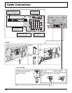
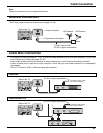
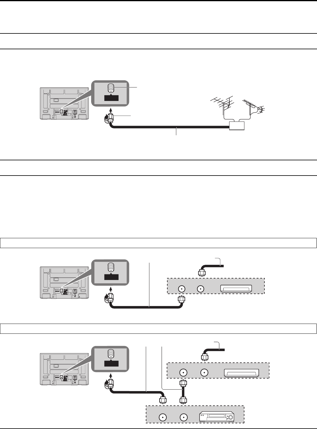
Antenna Connection
The RF input mode must be set to Antenna (see pages 19, 30).
Cable Connection
Note:
Cables and connectors are not supplied with this set.
Y
P
B
PR
Y
P
B
PR
COMPONENT VIDEO
INPUT
INPUT 1 INPUT 2OUTPUT
S VIDEO
12
L
R
VIDEO
AUDIO IN
AV IN
R L
AUDIO IN
DIGITAL
AUDIO OUT
SERVICE ONLY
ANTENNA
Cable In
IN
ANT
Mixer
UHF AntennaVHF Antenna
Back of the TV
75 Ohm Coaxial Cable
(5C-2V or higher specification)
Antenna Terminal
F-Type Antenna Connector
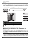
Cable Box Connection
• For reception of cable channels (01 - 135), connect the cable supplied by your local cable company. The RF input
mode must be set to Cable (see pages 19, 30).
• Certain cable systems offset some channels to reduce interference or view Premium (scrambled) channels.
A cable converter box is required for proper reception. Check with your local cable company for its compatibility
requirements.
• Set the TV channel to CH3 or CH4 when using this connection.
Cable Box
Y
P
B
P
R
Y
P
B
P
R
COMPONENT VIDEO
INPUT
INPUT 1 INPUT 2OUTPUT
S VIDEO
12
L
R
VIDEO
AUDIO IN
AV IN
R L
AUDIO IN
DIGITAL
AUDIO OUT
SERVICE ONLY
ANTENNA
Cable In
IN
ANT
Y
P
B
PR
Y
P
B
PR
COMPONENT VIDEO
INPUT
INPUT 1 INPUT 2OUTPUT
S VIDEO
12
L
R
VIDEO
AUDIO IN
AV IN
R L
AUDIO IN
DIGITAL
AUDIO OUT
SERVICE ONLY
ANTENNA
Cable In
IN
ANT
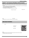
Incoming 75 Ohm Cable
from Cable Company
Back of the TV
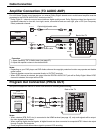
Incoming 75 Ohm Cable
from Cable Company
Back of the TV
CABLE BOX
OUTPUT
INPUT
CABLE BOX
OUTPUT
INPUT
VCR
ANT OUTPUT ANT INPUT
Cable Box and VCR
(5C-2V or higher specification)
(5C-2V or higher specification)


