A balanced line is a necessity if you are driving a long line to your preamplifier, and provided it is
equipped with balanced inputs. Balanced lines also reduce annoying hum in many areas prone to
RF interference, where 60 Hz (USA) or SO Hz (most overseas) television sync. signals can mimic
ordinary AC line "hum." In this case the two wires for the + and - audio signal are enclosed within
a third separate shield wire which is the "floating" ground.
Serious listeners prefer the superior musicality of balanced interconnections. The lower noise floor
seems to enhance the apparent width and depth of the soWld stage by reducing interference.
A Digital Output jack passes your digital source's data stream directly to a digital recorder like
a Mini Disc, DA T, DCC or CD.R. This is an RCA type connector; use only digital quality cable.
AC Power
Your DI AC-1500 has an IEC standard detachable power cord which has been specially selected for
its contribution to the sound quality of this unit. Try to connect only this cord directly to a nearby
AC wall outlet and avoid extension cords or connection to accessory outlets on your preamp.
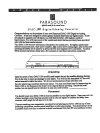
Operating your DI AC-1500
Power On/Off
Push the upper section of the button to turn on; lower section for off.
Sampling Frequency LEDs
Your DI AC-1500 will recognize the digital signal of whatever type of digital source you connect
and will switch to the correct sampling tate automatically. The 44.1 kHz sampling tate is standard
for compact discs. 32 kHz is for digital broadcast; 48kHz is for DA T.
Error/Data LED
In case there is an interuption of data from the digital source or a malfunction of the digital source
or connection, the ErrorIData LED will illuminate. This shows you that your DI AC-1500 is not
receiving correct digital data to process and convert to analog. In this case, a muting circuit will
prevent a "garbage" signal passed to Analog Out or the Digital Out Record jacks.
Input Select Buttons and LEDs
The four Input Select buttons correspond to the four input connectors on the rear panel:
Coaxial I, Coaxial 2, Optical I, Optical 2.
Polarity Invert Button and LED


