


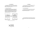


The Model 2026 and Model 2027 use a miniature configuration
switch package. To configure your unit, use a small screwdriver and
gently push each switch to its proper setting. The ON and OFF
positions are shown in Figure 2. Default settings for the DIP switches
are shown in the table on the following page. Detailed settings follow
the table.
3.2 DETAILED SWITCH SETTINGS
This section provides detailed information about the function of
each DIP switch and lists all possible settings.
Switch 1:
Hardware/Software
Control
The setting for Switch 1 determines whether these interface
converters will control either hardware or software flow control.
Switch 2:
Enable/Disable LED Indicator
The setting for Switch 2 determines whether the LED indicator is
enabled or disabled.
5
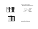
Flow Control SW1
Hardware OFF
Software ON
LED SW2
Enabled ON
Disabled OFF
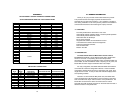
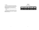
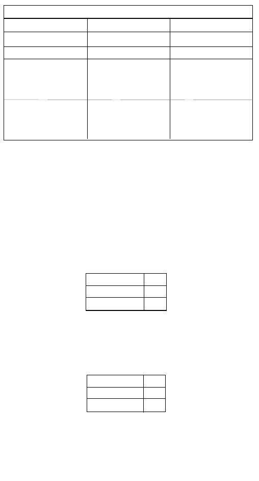
DIP SWITCH SUMMARY TABLE
Position Function Factory Default
SW1 Flow Control Off
SW2 LED Indicator On
SW3 Data, Parity, Stop Bits Off
SW4 Data, Parity, Stop Bits Off
SW5 Data, Parity, Stop Bits Off
SW6 Data Rate Off
SW7 Data Rate Off
SW8 Data Rate Off
Hardware
Enabled
8B, NP, 1S
9600 bps
}
}
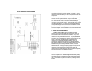
4.0 INSTALLATION
The Patton Model 2026 and 2027 are very simple to install. Once
you have configured the DIP switches, just plug your converter in to a
standard cable and you’re ready to go. Figure 3 illustrates the proper
connections for the Model 2026 and 2027. If you have special-ordered
a non-standard connector, your connections may be different.
8
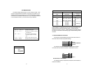
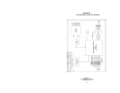
LED Codes
● ● — ● ——— ● ● — ● ——— Computer is sending data
● ——— ● ——— ● ——— Serial device is connected; computer is
not sending data
● ● ——— ● ● ——— Both serial and parallel devices are
connected; computer not sending
data
● — ● ——— ● — ● ——— Printer not ready, data held in buffer
● ● ● ● ———● ● ● ● Computer ignoring flow control, data lost
Key:
● Blink
— Short pause
——— Long pause