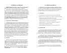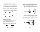
3.2.1 CONFIGURATION SWITCH FUNCTIONS
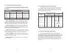
The table and descriptions below detail the functions of the five
configuration switches. Read this information carefully before setting
the switches.
SW1-1: RTS/CTS Delay: Switch 1-1 determines how long cir-
cuit CB (CTS) takes to become active after RTS is asserted (DCE
Mode only). RTS delay of 8 mSec will give any signal from any other
device time to clear the transmit line. In DTE mode, CTS is open.
SW1-2: Echo Enable: With Switch 1-2 in the ON position, the
285 echoes transmitted data back to the transmitting device. This is
so the user can see what is being transmitting to the remote device.
(Typically used in half duplex modes only).
SW1-3: Carrier: With Switch 1-3 in the ON position, the 285
transmitter operation follows circuit CA (Request to Send). When RTS
is low, the 285 transmitter operation is off (0V) (DCE mode only).
SW1-4: Impedance: Switch 1-4 defines a termination resist-
ance.The 285 transmitter can drive 50 unit loads including two termina-
tionresistances of 120 Ohms each.
SW2: 2 Wire/ 4 Wire: Switch 2 determines 2 wire (half duplex)
or 4 wire operation.
5
3.2.2 CONFIGURATION SWITCH APPLICATIONS
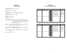
The table below shows you how to set the Model 285's configu-
ration switches to fit several common applications. If you have any
questions about the proper settings for your application, call Patton
Technical Support at (301) 975-1007.
*NOTE: RTS/CTS Delay (SW1-1) setting should be based upon transmission timing.
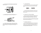
3.2.3 WHEN YOU'RE FINISHED CONFIGURING...
Once you've finished setting the Model 285's configuration
switches,
pause
before you snap the case halves back together. If you
are connecting the RS-485 interface using the internal terminal blocks,
go to Section 4.1.3 and continue the installation procedure. If you are
connecting the RS-485 interface using RS-11, RS-45 or DB-25, go
ahead and snap the case halves back together now (don't force a fit—
make sure all the pieces are properly set before snapping the case
halves shut).
6
RTS/CTS (SW1-1)* ON ON ON ON ON
Echo (SW1-2) OFF ON OFF ON OFF
Carrier (SW1-3) OFF ON ON Master-OFF ON
Slaves-ON
Impedance (SW1-4) ON ON ON Master - ON
Slaves - HIGH
Last Slave - ON
2wire/4wire (SW2) ON ON OFF ON OFF
TYPICAL SWITCH APPLICATIONS
Point-to-Point
Switch
Settings
Multi-point
4W 2W 4W 2W4W HDX
SWITCH SUMMARY TABLE
Position Function Off Position On Position
SW1-1 RTS/CTS Delay 0 mSec 8 mSec
SW1-2 Echo Enable Echo "Off" Echo "On"
SW1-3 Carrier Control Constantly "On" Controlled by RTS
SW1-4 Impedance High (120K Ohm) Low (120 Ohm)
SW2 2 wire/4 wire 2-wire 4-wire


