


5.2 TEST MODES
The Model 305X Series has three test modes: Local Loopback,
Remote Loopback and DTE Remote Loopback. This section tells you
how to use these test modes to isolate cabling or multiplexer problems.
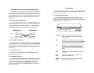
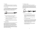
5.2.1 Local Loopback
The Local Loopback test allows you to evaluate the integrity of the
DTE cable and the local Model 305X. Any data sent to the local Model
305X in this test mode will be echoed (returned) back to the user
device. (See Figure 8, below.) For example, characters typed on the
keyboard of a terminal will appear on the terminal screen.
To use the local loopback test, follow these instructions.
1. Set the front panel switch of the mux being tested to local
loopback. The corresponding LED should glow.
2. On a terminal connected to one of the sub-channel ports, key
a character string. You should see those same characters
echoed back on the terminal screen.
3. If the keyed character string does not echo on the terminal
screen, check all sub-channel connections for continuity and
proper pinning.
5.2.2 Remote Loopback
The Model 305X offers a second test that evalulates the integrity of
the local and remote multiplexers. With the local multiplexer in
REMOTE LOOPBACK mode and the remote multiplexer set to
NORMAL, the local mux sends a low frequency pulse to the remote
mux over the twisted pair wire. If the two muxes and the twisted pair
cable are functioning properly together, you will see the remote
multiplexers RECEIVE DATA LEDs blinking together. If you have a RJ-
45 loopback adapter connected to the remote sub-channel ports, the
remote multiplexers TRANSMIT DATA LEDs and the local multiplexers
RECEIVE DATA LEDs will also blink.
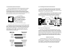
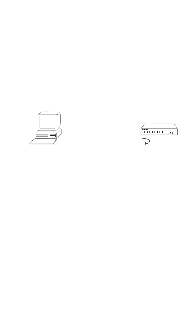
5.2.2 DTE Remote Loopback
The DTE Remote Loopback test allows you to evaluate the
multiplexers and their connection path by using the local DTE. In order
to fully test both units as well as the twisted pair connection path, you
will need install the enclosed RJ-45 loopback adapter into the specific
remote sub-channel modular jack. Figure 9 shows an example of the
Remote Loopback test with the RJ-45 loopback adapter attached to the
remote multiplexer.
To use this test follow the instructions below:
1. Install the RJ-45 loopback adapter into the sub-channel of
the remote multiplexer as shown above in Figure 9. For
instance, if you are testing channel 1, install a loopback
adapter into the sub-channel 1 RJ-45 jack on the remote
multiplexer.
2. Set the front panel switch of the local multiplexer and the
remote multiplexer to NORMAL.
3. On a terminal connected to the sub-channel port to be tested,
key a character string. You should see those same characters
echoed back on the terminal screen after they have passed
through the local multiplexer, through the cable and remote
multiplexer, and then back to the through the cable to the
multiplexer and the attached terminal.
4. If the above test exhibits bit errors or does not work at all,
check all sub-channel and main channel connections for
continuity an proper pinning.
Figure 9 . Line Test
Figure 8. Local Loopback Test
11
12