


9
10
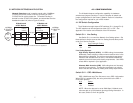
Switch S1-3 : Clear Channel Mode
When S1-3 is at Off position, the K Module is running in G.703
clear channel mode. When S1-3 is at On position, the K Module is run-
ning in G.704 framed mode. When the K Module is set to framed
mode, channel 0 will be used to pass G.704 framing information which
results in a maximum bandwidth of 1984kbps for user data.
S1-3 Option
Off Clear Channel Mode (G.703)
On Framed Mode (G.704)
Switch S1-4 Through S1-8 : Reserved
Reserved for future use and should be set to OFF.
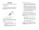
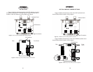
4.2 Jumper Configuration
The Patton K Module has four jumpers (two position headers):
JP4, JP5, JP6, and JP7. These jumpers are used to select input and
output impedance matching between the module and external line. See
Appendix E for jumper locations.
The following is a description of the jumper settings with respect
to the front panel connectors.
1. For a 75 ohm connection (coax) install JP4 - JP7 (
default
).
2. For a 120 ohm connection (RJ-48C) remove JP4 - JP7.
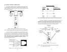
4.3 Configuring Your Model 1095 mDSL Modem
This section describes how to configure your mDSL modem for
use with an IM1/K (Model 1095) or an IM2RC/K (Model 1095RC).
The K Module requires the 1095/1095RC to have software ver-
sion 2.3.2 or later, which began shipping on 04/01/00.
If you are unsure of the software revision of your unit, please con-
tact Patton Electronics Technical Support.
Clock Mode
The mDSL modem must be set for the External Clock mode when
a K Module is installed. The modem will always receive the clocking
from the K Module. If you are configuring a Network Extension applica-
tion, set both modems for External Clock mode. If you are configuring
a Network Termination application, please set the modem with the K
Module for External Clock and the unit with the serial/Ethernet inter-
face for Receive Recovered clock mode. In order to determine the
switch settings specific to your unit, refer to the mDSL manual that was
shipped with your unit.
CO-CP
The CO/CP selection tells the units which modem will begin the
handshaking for the link. In all applications one unit must be set for CO
and one unit must be set for CP, they work in pairs. A mDSL modem
set for either Internal or External clock mode will automatically default
to the CO mode. A mDSL modem set for Receive Recovered clock
mode will automatically default to the CP mode. If you are configuring
a Network Extension application, you must force one of the units to
CP mode by setting S2-1 on the mDSL modem to the ON position.
Note that the mDSL manual refers to this switch as "Reserved". If you
are running in the Network Termination mode, no extra configuration is
required.
Interface Type
The mDSL modem requires that the interface type is specified.
Any unit that has a K Module installed must be set to G.703/G.704
Interface. This is done by setting S2-5 on the mDSL modem to ON.
Note that the mDSL manual refers to this switch as "Reserved".
DTE Rate for the mDSL Modems
To select the number of G.703/G.704 channels to be carried
across the link, multiply the number of required channels by 64Kbps
and then set the DTE rate of the mDSL modem to that number. The
mDSL modem will then carry that number of channels from the
G.703/G.704 line, starting with channel 1 (Note channel 0 is used for
G.704 framing information) across the DSL link. For example, if you
want to carry 4 channels across the DSL link, set the mDSL DTE Rate
to 256Kbps (4 x 64Kbps = 256Kbps). The mDSL modem and the K
Module will then carry channels 1 - 4 across the DSL link.
If you are running in clear channel mode, set switch S1-3 on the K
Module to "clear channel" and set the DTE Rate of your mDSL modem
to 2048Kbps.