6 of 24
ISSUED: 06-10-05 SHEET #: 095-9225-8 09-25-06
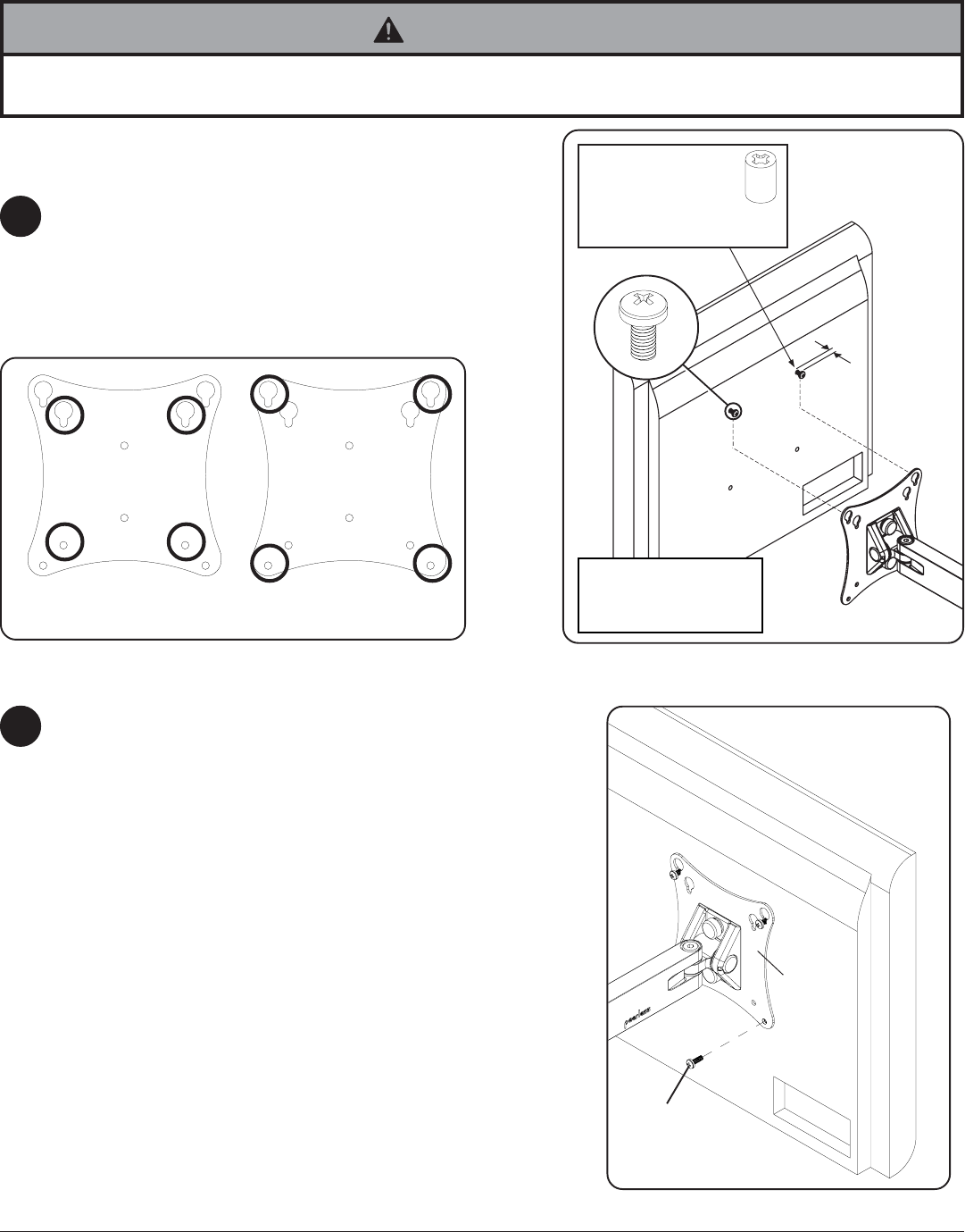
Insert two M4 x 12 mm screws (F) into top two holes
of screen, leaving approximately 1/4" of exposed
thread. Hook screws onto keyslots of adapter plate
as indicated in figures 2.1 and 2.2.
*Note: If hole pattern is in a pocket, insert two M4 x
20 mm screws (G) with two retaining spacers (H)
into top two holes of screen as indicated right.
2
3
fig. 2.1
• If screws don't get three complete turns in the screen inserts or if screws bottom out and bracket is still not tightly
secured, damage may occur to screen or product may fail.
WARNING
Note: To add security, order ACC 918 for security
screws. Refer to ACC 918 instruction sheet for
installing security screws.
1/4"
H
*For screens with a
hole pattern in a
pocket, spacers (H)
go between adapter
plate and screen.
FOR VESA
®
75
MOUNTING PATTERN:
FOR VESA
100
MOUNTING PATTERN:
fig. 2.2
F
Screen may appear
slightly different than
illustrated
Insert one M4 screw (F or G) through bottom hole of
adapter plate as shown in figure 3.1.
fig. 3.1
F or G
ADAPTER
PLATE


