


ISSUED: 8-29-07 SHEET #: 124-9102-3 08-13-08
Visit the Peerless Web Site at www.peerlessmounts.com For customer care call 1-800-865-2112 or 708-865-8870.
5 of 5
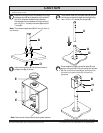
Identify hole pattern on back of screen.
Note: Desktop mount only supports screens with a VESA 100, VESA 200 and VESA 400 hole pattern.
FOR VESA
®
100 MOUNTING PATTERN:
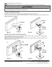
Thread four screws (I or J) into screen leaving 1/8" exposed thread as shown in figure 5.1.
Hook screen onto keyhole slots of adapter box (B), then fasten four screws (I or J) through the back of adapter box into
adapter plate as shown in figure 5.2.
FOR VESA
®
200 and VESA
®
400 MOUNTING PATTERN:
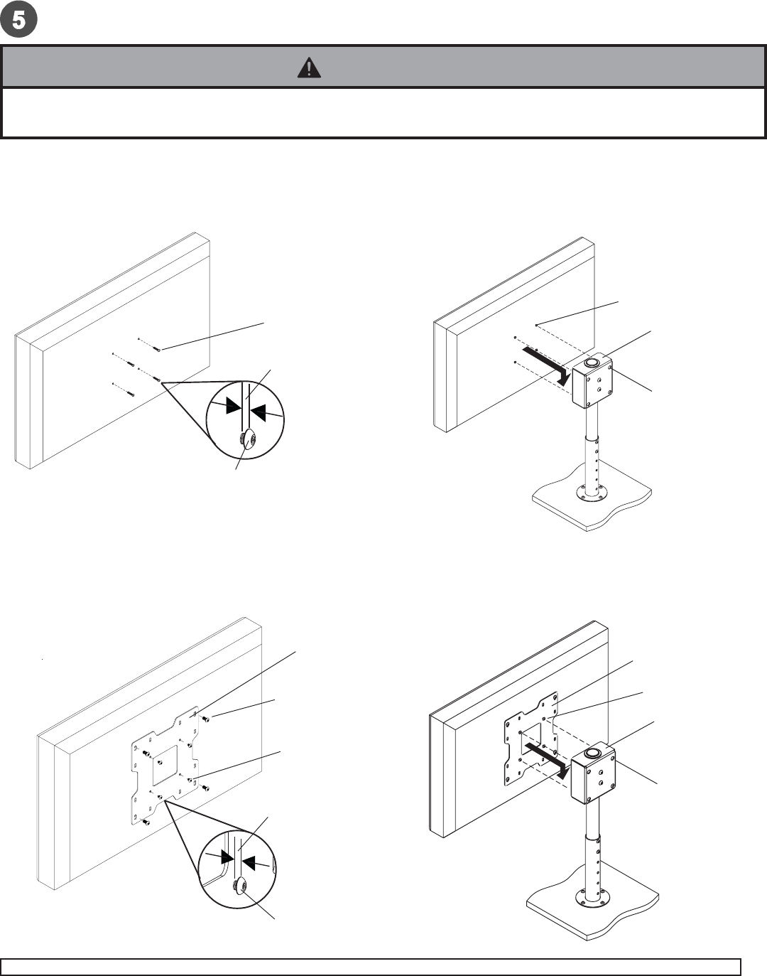
Attach adapter plate to screen using four screws (K, L or M). Thread four M5 x 6 mm screws (F) into adapter plate
leaving 1/8" exposed thread as shown in figure 5.3.
Hook screen onto keyhole slots of adapter box (B), then fasten four screws (F) through the back of adapter box into
adapter plate as shown in figure 5.4.
• If screws don't get three complete turns in the screen inserts or if screws bottom out and bracket is still not tightly
secured, damage may occur to screen or product may fail.
WARNING
fig. 5.1
fig. 5.2
fig. 5.3
fig. 5.4
1/8" SPACE
I or J
TIGHTEN
FASTENERS
THROUGH
BACK HOLES
1/8" SPACE
A
K, L or M
F
F
TIGHTEN
FASTENERS
THROUGH
BACK HOLES
B
I or J
© 2008, Peerless Industries, Inc. All rights reserved.
All other brand and product names are trademarks or registered trademarks of their respective owners.
I or J
A
B
F