


7 of 23
ISSUED: 02-05-09 SHEET #: 201-9421-9 06-03-09
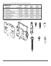
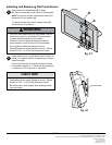
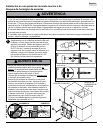
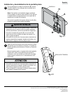
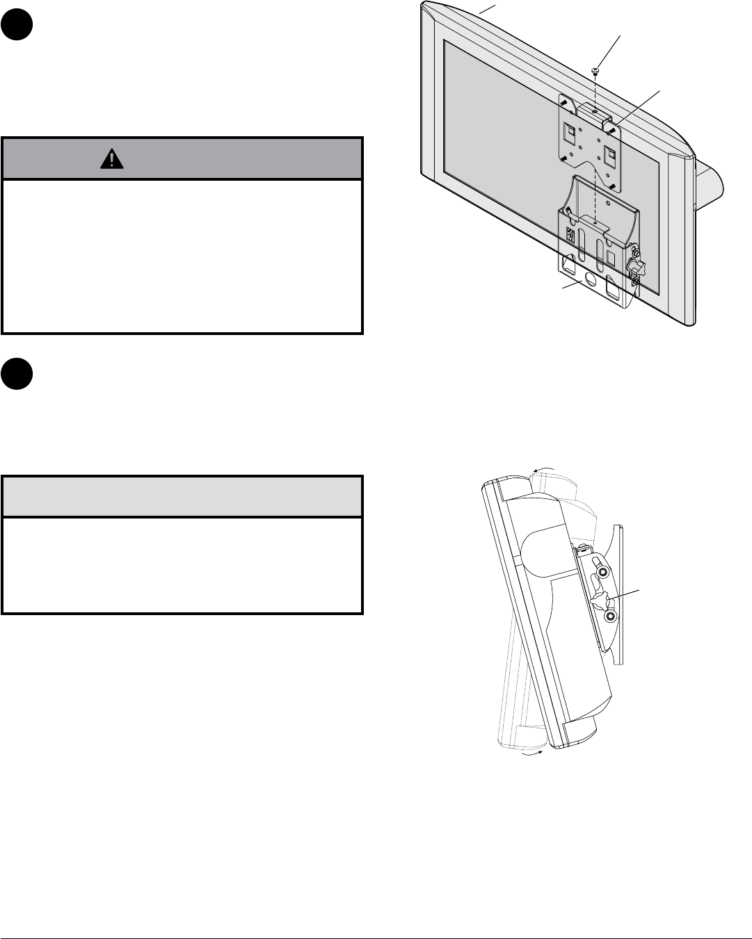
Attach screen to tilt assembly (B). Tighten
M5 x 6 mm screw (H) to lock screen to tilt assembly.
Note: For security models, use security driver (I) to
tighten M5 x 6 mm screws (H).
To remove screen from mount, loosen screw (H)
and lift screen off of mount.
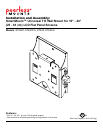
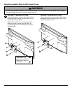
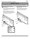
Installing and Removing Flat Panel Screen
3
• Do not lift more weight than you can handle. Use ad-
ditional man power or mechanical lifting equipment
to safely handle placement of the screen.
• Failure to lock hook plate (A) with screw (H) can
cause screen to come off mount if hit accidentally.
• Do not tighten screws with excessive force.
Overtightening can cause damage to mount. Tighten
screws to 20 in. • lb (2.26 N.M.) maximum torque.
WARNING
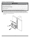
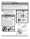
Adjust tension knob on right side of mount shown in
gure 4.1 to desired tension to balance your screen
size and weight.
Push or pull from top or bottom of screen to adjust
tilt as shown in gure 4.1. The tilt can be adjusted to
a maximum of 15° forward or 5° backward.
4
• Do not tighten screws with excessive force.
Overtightening can cause damage to mount. Tighten
screws to 40 in. • lb (4.5 N.M.) maximum torque.
• Be careful not to pinch ngers when pushing screen
from the bottom.
CAUTION
g.4.1
TENSION KNOB
A
SCREEN
H
B
g.3.1
© 2009, Peerless Industries, Inc. All rights reserved.
All other brand and product names are trademarks or registered trademarks of their respective owners.
Peerless Industries, Inc.
3215 W. North Ave.
Melrose Park, IL 60160
www.peerlessmounts.com