C2928M-QS (7/05) 3
Chassis Assembly
Unpack the PMCD750 unit. The screen is not needed yet and should be left in its container at this time.
SINGLE DISPLAY
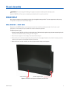
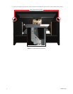
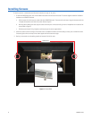
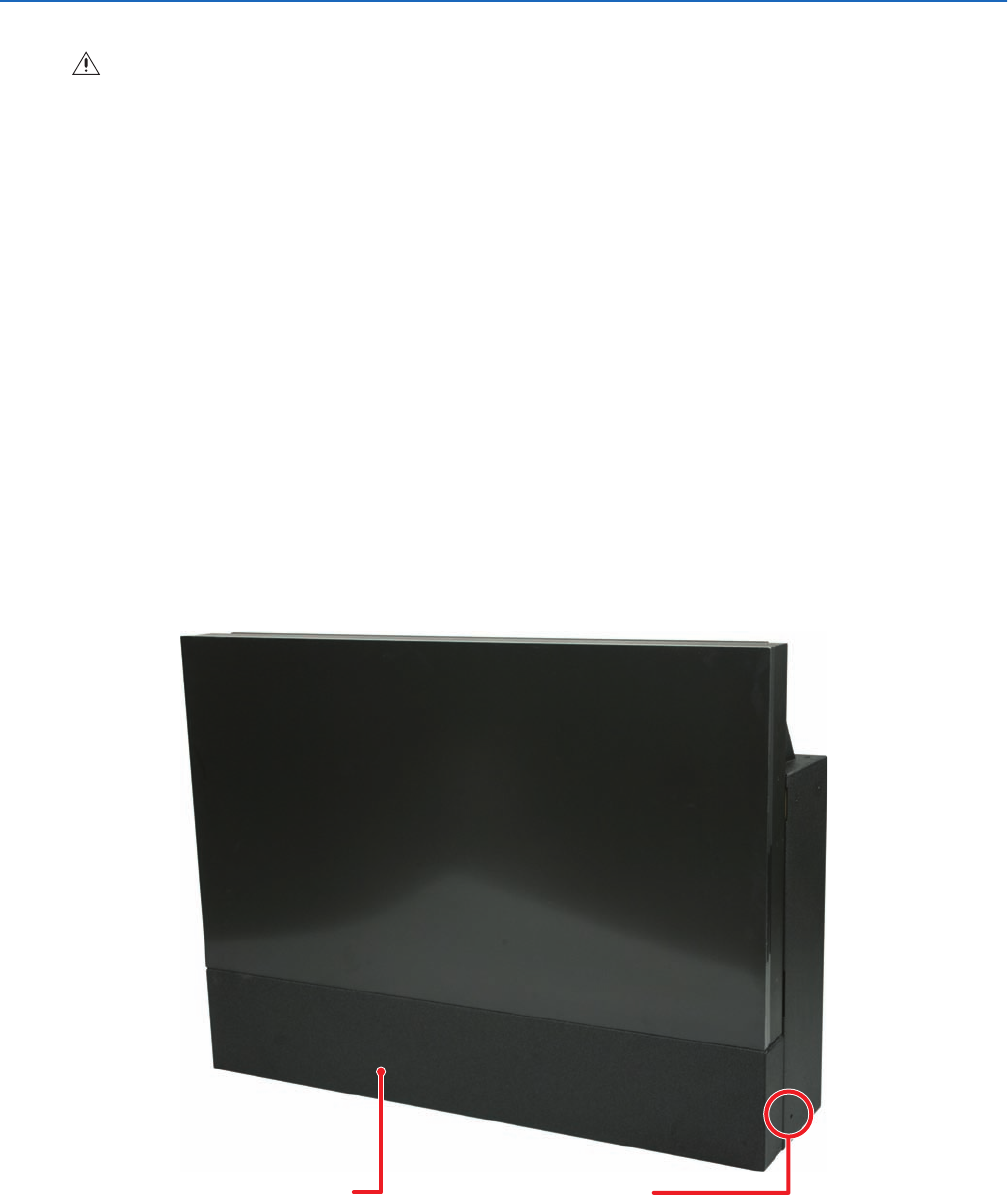
Attach the screen support to the front edge of the chassis with the supplied screen support bolts. The screen support mounts only one way.
It incorporates a stop (rest) for the screen. Refer to Figure 1.
WALL DISPLAY – FIRST ROW
Straightness of the PMCD750 display is critical because the screens have no mullion (outside screen border). If the first row in a wall
configuration is not horizontally straight, the problem will worsen as construction progresses.
To build the first row of a wall:
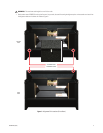
1. Set the first row of PMCD750 units side by side without the screens. Bolt them loosely together through the bottom connection points with
the 1/4-20 x 3.5-inch bolts, washers, and wing nuts. Refer to Figure 1.
2. Attach the screen supports to the front edge of each chassis. Refer to Figure 1.
3. Check the first row for horizontal straightness by making sure the front and top edges of adjacent units are flush. If necessary, use shims
under the units to make sure the top edges of adjacent units are flush.
4. When the first row is straight horizontally and vertically, tighten the bolts holding the units together.
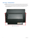
Figure 1.
Mounted Screen Support and Bottom Connection Point
WARNING:
The chassis weighs 65 lb (29.5 kg). Two people are required to handle and position the display safely.
SCREEN SUPPORT
BOTTOM CONNECTION POINT


