Pelco Manual C907M-A (7/96) 3
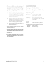
6. There are two Phillips screws (I) on the bottom of
the enclosure. If you are installing a WLV500 re-
ceiver, they are not used. If your are installing a
WLV2000 receiver, they are test points for mea-
suring Received Signal Strength Indication (RSSI).
Wire the test points as follows:
a. Solder one end of a wire to the solder lug on
receiver mounting plate. Solder the other end
of the wire to the solder lug on the Phillips
screw on the left (the screw to the left of I) on
the bottom of the enclosure.
b. Solder one end of a wire to the solder lug on
the Phillips screw on the right (I) on the bot-
tom of the enclosure. Screw the other end of
the wire into the tip plug that is supplied.
c. Push the tip plug into the green connector on
the front of the receiver.
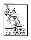
7. Attach the receive antenna (18) to the antenna
mounting bracket (16).
8. Screw the connector on the end of the antenna cable
onto the mating connector on the top of the receiver.
9. Close the lid.
10. To complete the installation, refer to the instruc-
tions for outdoor installation in your WLV500 or
WLV2000 manual.
5.0 SPECIFICATIONS
Power Input: 24, 120, or 230 VAC
Construction: Fiberglass box with NEMA 4X rat-
ing
IEC 144 Rating: IP66
Dimensions: 4.3" H x 11.5" L x 9.5" W
(10.92 x 29.21 x 24.13 cm)
Cable Entry: One (1) gland for power cord
Two (2) glands for video and audio
coaxial cable
Locking
Method: Latches with holes for padlocks
Weight (excluding wireless transmitter or receiver)
Enclosure: 8.6 lbs (3.90 kg)
Shipping: 10.6 lbs (4.81 kg)


