


6 Pelco Manual C520M Rev B (6/92)
6.0 MAINTENANCE
Under normal operating conditions and usage, mainte-
nance of this equipment is not necessary. However, if
maintenance is required, contact a Qualified Service
Technician or return to the factory for repair.
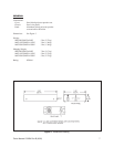
7.0 SPECIFICATIONS
CONTROLS
Pan/Tilt: 8-position joystick (Up, down, left,
right and simultaneous combinations
of pan/tilt functions when joystick is
positioned diagonally between two
functions)
Auto/Random
Scan: 3 position rocker switch:
– AUTO/RANDOM
– ON (manual)
– OFF
Pilot Lamp: Long life neon
ELECTRICAL
Input Voltage: 120 VAC or 230 VAC, 50/60 Hz
Auto/Random
Circuit: A noise generator drives a scan/dwell
flip-flop which is logically anded with
a direction flip-flop causing random
scan and random dwell periods as
well as random scan direction. Upon
limit switch activation, a current sens-
ing circuit detects the absence of the
motor drive circuit and reverses scan
direction.
Output Voltage:
24 VAC MPT24DT, MPT24DT/220,
MPTA24DT, MPTA24DT/220
120 VAC MPT115DT, MPTA115DT
230 VAC MPT220DT, MPTA220DT
Fuse Protection: 1 amp SB
Power Cord: 3-wire grounded, #18 Awg
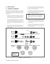
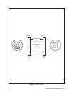
Connectors: Amp CPC type, 14-pin (mate supplied)
Conductor
Requirements: 5 plus ground (no additional conduc-
tors for auto/random scan)
Cable Distances: Refer to the specifications for the spe-
cific pan/tilt to be used with the control.