


2 Pelco Manual C325M-C (6/99)
REVISION HISTORY
Manual # Date Comments
C325M-C 10/98 Changed manual to new format. Added ratings. Revised
installation instructions. Moved exploded assembly dia-
gram, parts lists, and potentiometer adjustment to main-
tenance/service manual. Reversed wire colors for pins 5
and 8 in wiring schematics.
6/99 Revised Figures 3 & 4 to include wiring for HB option.
CONTENTS
Section Page
1.0 GENERAL ..................................................................................................3
1.1 IMPORTANT SAFEGUARDS AND WARNINGS ...............................3
2.0 DESCRIPTION ..........................................................................................4
2.1 MODELS ............................................................................................4
2.2 OPTIONS ...........................................................................................4
2.3 RATINGS ...........................................................................................4
3.0 INSTALLATION ..........................................................................................5
3.1 MOUNTING .......................................................................................5
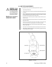
3.2 CAMERA/ENCLOSURE MOUNTING ...............................................5
3.3 WIRING .............................................................................................5
3.3.1 Mating Connector Assembly ................................................. 7
3.4 LIMIT STOP ADJUSTMENTS ...........................................................10
4.0 OPERATION .............................................................................................11
5.0 TROUBLESHOOTING ..............................................................................12
5.1 SERVICE MANUAL ..........................................................................12
6.0 MAINTENANCE ........................................................................................13
6.1 Tightening Drive Chains....................................................................13
6.2 Chain Drive Lubrication ....................................................................13
7.0 SPECIFICATIONS ....................................................................................14
8.0 WARRANTY AND RETURN INFORMATION ...........................................16
LIST OF ILLUSTRATIONS
Figure Page
1 Sealant Locations ..............................................................................5
2 Connector Assembly ..........................................................................7
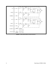
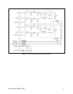
3 PT550P Wiring Diagram ....................................................................8
4 PT550P/PP Wiring Diagram ..............................................................9
5 Limit Stops ........................................................................................10
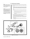
6 Servicing the Pan/Tilt ........................................................................13
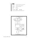
7 PT550P Series Dimension Drawing.................................................. 15
LIST OF TABLES
Table Page
A Maximum Cable Distances ................................................................6