


Perle C/CM-10GT Media Modules Installation Guide
5
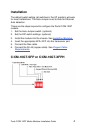
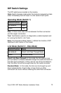
DIP Switch Settings
The DIP switches are located on the module.
Note: Switch changes made when the module is powered up take
effect immediately and will result in a link reset on both ports.
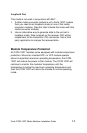
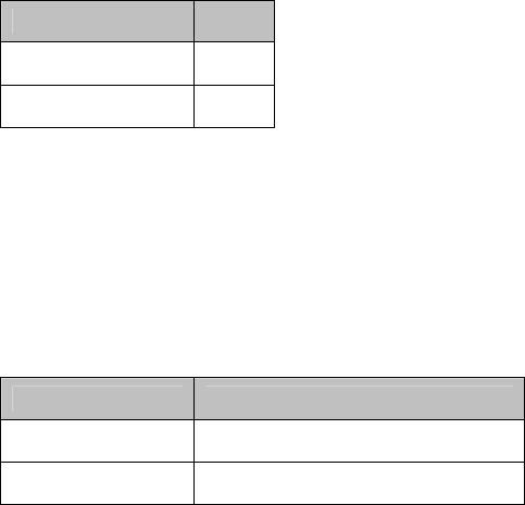
Operating Mode (Switch 1)
Switch Position Mode
Up (default) Data
Down Test
Data: In Data mode, data will flow between the fiber connection
and the copper connection.
Test: Test Mode is used to run diagnostics, enable loopback and
for running the Built In Link Tests.
Note: The Operation Mode (Switch 1) affects the function of DIP
Switches 2 and 3 when in Test mode.
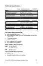
Link Mode (Switch 2 – Data Mode)
Switch Position Mode
Up (default) Smart Link Pass-Through Mode
Down Standard Mode
Smart Link Pass-Through: In this mode, the link state on one
port connection is directly reflected through the media converter to
the other port connection. If link is lost on one of the connections,
then the other link will be brought down by the media converter.
Standard Mode: In this mode, the links can be brought up and
down independently of each other. A loss of link on either
connection can occur without affecting the other fiber connection.