


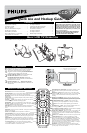

HOOKING UP THE TELEVISION
4
T
he Monitor (Audio/Video) out jacks are great for recording with a
VCR or used to connect an external audio system for better audio.
For Audio System Connection:
1
Connect one end of the R(ight) and L(eft) AUDIO (Monitor
Out) jacks located on the right rear of the TV to the R and L
audio input jacks on your sound system.
2
Turn the TV and audio system ON. TV sound can be heard
through the audio system.
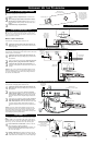
MONITOR OUTPUTS
PC
Audio
Out
VGA/RGB
Out
1
2
3
4
DVI
T
his TV can be used as a PC Monitor. Your computer will have
to be equipped with a VGA type video output and VGA cable.
1
Connect one end of the VGA Video cable to the Monitor
(video) output on the computer to the PC Input (VGA) jack
on the bottom of the TV. You can use the DVI cable if your
computer has DVI capability.
2
Although audio connections are not required, the TV can
reproduce the computers audio out by an AUDIO
ADAPTER to the Audio output jack on the computer (if
available) while connecting the other ends of the Audio
cables to the Audio In left and right (PC/HD) Input Jacks
on the bottom of the TV.
3
Turn the TV and the Computer ON.
4
Press the PC Mode button to set the TV into the HD
Mode and tune to the computer’s signal.
Note: Please contact your dealer or Philips at 800-531-0039 for
information about purchasing the needed cables.
PC (MONITOR) INPUTS
AUDIO
ADAPTER
VGA CABLE
BOTTOM OF TV
DVI CABLE
T
here are Audio/Video Input Jacks located on bottom of the TV can
also be used for extra accessory device connections for items such
as cameras or gaming stations.
1
Connect the VIDEO (yellow) adapter cable to the VIDEO
AV2 in jack on the left rear of the TV. Connect the other end
of the VIDEO (yellow) cable to an RCA type VIDEO Cable.
Connect that cable to the VDEO OUT jack on the back of the
accessory device being used. Note: An S-Video cable can be
used in place of the yellow Video cable if your device is
equiped with an S-Video Output. S-Video provides better video
playback.
2
Connect the AUDIO (red and white) adapter cable to an
RCA type Audio Cable. Connect the other ends of the
AUDIO (red and white) cables to the AUDIO (left and right)
OUT jacks on the rear of the accessory device being used.
3
Turn the accessory device and the TV ON.
4
Press the AV+ button and the number 2 button on the
remote control to select the AV2 channel for the accessory
device. AV2 will appear in the upper left corner on the TV
screen when tuned properly.
5
With the accessory device ON, press the PLAY button to acti-
vate the playback on the television.
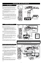
AV2 INPUTS
M
uch like the AV2 jacks, the AV3 jacks allow for extra accessory
device connections for items such as cameras or gaming stations.
The AV3 Input Jacks are located on the side of the TV.
1
Connect the VIDEO (yellow) adapter cable to the VIDEO
AV3 in jack on the left rear of the TV. Connect the other end
of the VIDEO (yellow) cable to an RCA type VIDEO Cable.
Connect that cable to the VIDEO OUTjack on the back of the
accessory device being used. Note: An S-Video cable can be
used in place of the yellow Video cable if your device is equiped
with an S-Video Output. S-Video provides better video play-
back.
2
Connect the AUDIO (red and white) adapter cable to an
RCA type Audio Cable. Connect the other ends of the AUDIO
(red and white) cables to the AUDIO (left and right) OUT
jacks on the rear of the accessory device being used.
3
Turn the accessory device and the TV ON.
4
Press the AV+ button and the number 3 button on the
remote control to select the AV3 channel for the accessory
device. REAR will appear in the upper left corner on the TV
screen when tuned properly.
5
With the accessory device ON, press the PLAY button to acti-
vate the playback on the television.
AV3 (SIDE) INPUTS
VIDEOAUDIO
RIGHT LEFT
S-VIDEO
4
3
2
1
3
AUDIO CABLES
(Left and Right)
VIDEO CABLE
ACCESSORY DEVICE
JACK PANEL
ACCESSORY DEVICE
(Camera., DVD, VCR, etc.)
4
2
1
1
OR
3
3
VIDEOAUDIO
RIGHT LEFT
S-VIDEO
A
U
X
/
T
V
I
N
P
U
T
P
H
O
N
O
I
N
P
U
T
R
L
1
2
ACCESSORY DEVICE
(Camera., DVD, VCR, etc.)
JACK PANEL
SIDE OF TV
AUDIO
CABLES
(Left and
Right)
S-VIDEO CABLE
ACCESSORY DEVICE
JACK PANEL
Audio System Connection:
AUDIO CABLES
(Red & White)
AUDIO SYSTEM
with AUDIO INPUTS
AV OUT
AUDIO L(eft) and R(ight)
JACK PANEL
BOTTOM OF TV
OR
AUDIO CABLES
VIDEO CABLE
AN S-VIDEO CABLE CAN
BE USED IN PLACE OF THE
YELLOW VIDEO CABLE IF
DESIRED.
S-