


49
ANT "A"
75Ω
L
Monitor out
VIDEO
S-VIDEO
PIP ANT "B"
75Ω
SURROUND SOUND
88
+ R – – L +
AV1 in
Y
Pb
Pr
AV2 in
AUDIO
R
M-Link
1
ANTENNA
OUT
ANTENNA
IN
VIDEO
AUDIO
IN
IN
OUT
OUT
L
R
OR
2
4
3
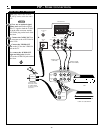
AC-3(ANALOG OFF)
PCM(ANALOG ON)
AUDIO OUT
AUDIO SELECTION
PCM/
AC-3 DIGITAL
1
2
R
L
ANALOG
VIDEO
S
VIDEO OUT
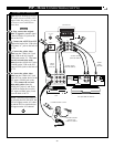
T
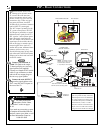
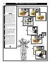
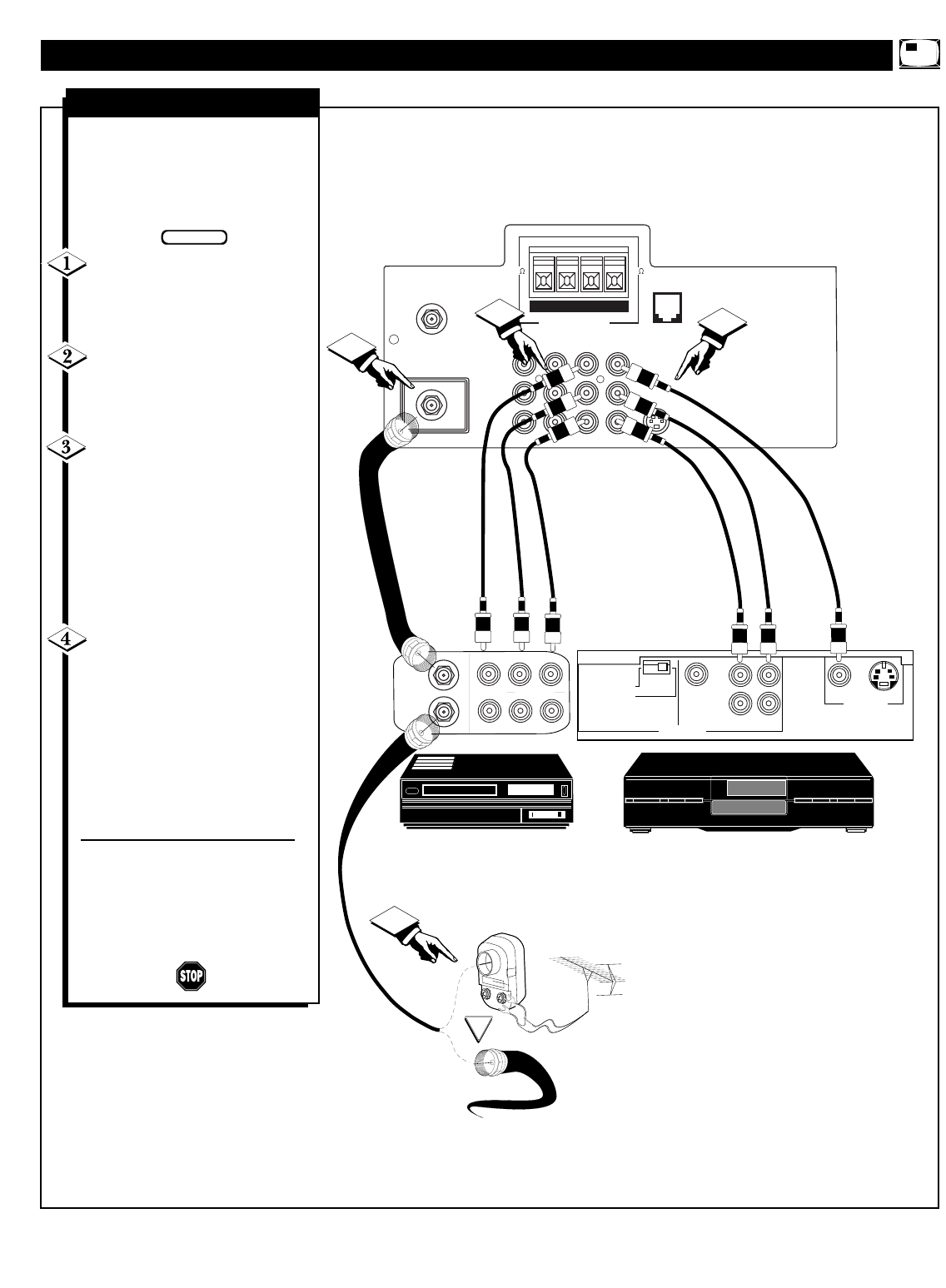
he steps for hooking up a VCR
(video cassette recorder), DVD
(digital video disc player), or simi-
lar device to work with PIP are
shown here.
First, connect the original
cable TV signal or antenna signal
to the ANTENNA IN jack on the
back of the VCR.
Connect the ANTENNA OUT
jack on the back of the VCR to the
ANT(enna) ÒAÓ jack on the back of
the TV.
Connect the yellow video
cable from the VIDEO OUT jack
on the VCR to the AV1 in(put)
VIDEO jack on the TV. Then con-
nect the red and white audio
cables from the AUDIO OUT jacks
(L and R) on the VCR to the AV1
in(put) AUDIO jacks on the back of
the TV.
Connect the yellow video
cable from the VIDEO OUT jack
on the DVD or similar device to the
AV2 in(put) VIDEO jack on the
TV. Then connect the red and
white audio cables from the
AUDIO OUT jacks (L and R) on
the DVD or similar device to the
AV2 in(put) AUDIO jacks (L and
R) on the back of the TV.
NOTE: Remember that when you
are selecting the PIP SOURCE, the
VCR will appear on the AV1 chan-
nel and the DVD or similar device
will appear on the AV2 channel.
PIP – MORE CONNECTIONS (CONT’D)
BEGIN
BACK OF TV
AUDIO CABLES
(RED AND WHITE)
VIDEO
CABLE
(YELLOW)
VCR
DVD (OR SIMILAR DEVICE)
VIDEO
CABLE
(YELLOW)
OUTSIDE UHF/VHF
ANTENNAOR
CABLE TV SIGNAL
75-OHM COAXIALCABLE
AUDIO CABLES
(RED AND WHITE)
VCR and DVD Connections