


Picture Tube Replacement
Refer to CRT Assembly Exploded View
Replacement of the cathode ray tube (CRT) and/or optical system components of a Projection TV (PTV) can be
easily accomplished by following general guidelines. Use care when working around the CRT and optical
systems of the PTV. The PTV light path encompasses a number of precision optical components. These include
lenses, mirrors, the lenticular screen, and fresnel lens. The PTV incorporates three separate CRTs,
representing green, red, and blue outputs. Each CRT uses an independent deflection/convergence yoke,
magnetic centering ring, coupler, C-element lens, and output lens (A/B lens). Each tube is mechanically
fastened to a coupler which houses fluid (a glycol-type substance) used to cool the high temperatures
generated by the small (7") CRTs. The fluid also provides an optical characteristic supporting the optical system
of the PTV. When replacement of a CRT or optical component is required, caution must be exercised in
preventing fluid spillage. The technician must carefully reassemble the CRT/optical components, ensuring a
proper seal of the coupling fluid. Use only factory original coupling fluid.
Caution: Do not use or add water as an alternative to the prescribed coupling fluid.
The following procedure should be used when performing repairs on the CRT/optical assemblies of the
Projection TV.
Note: Upon completion of CRT/optical assembly repair, the centering, convergence, gray scale, mechanical
and electrical focus adjustments are required. If more than one assembly requires repair, it is recommended the
service technician fully complete one assembly at a time, using the existing assemblies as a reference for the
alignment of the centering and convergence.
A. Single CRT/Lens Assembly from the Light Rack
1a) Remove AC power from the PTV.
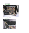
2a) Remove the upper and lower back covers (1/4" screws).
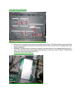
3a) Remove the barrier board and the shield cover from around the lens assemblies (1/4" screws).
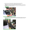
4a) Carefully remove the CRT Socket Board from the CRT of the CRT/optical assembly being serviced.
5a) Remove the yoke and convergence plugs, of the CRT/optical assembly being serviced, from the Large
Signal Module.
6a) Remove the high voltage anode lead from the HV splitter block on the Large Signal Module of the
CRT/optical assembly being serviced. Remove ground lug connectors from the coupler frame.
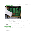
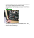
7a) Remove the four 1/4" screws that secure the CRT/lens assembly to the light rack. These four screws are
located in each corner, on the top of the coupler assembly.
Caution: Do not remove the bolts with pressure springs or the inverted Torx screws of the CRT/lens assembly.
The removal of these components could result in fluid spillage into the PTV cabinet.
8a) Carefully remove the CRT/lens assembly from the PTV cabinet.
Servicing the CRT/Optical Assembly
Caution: Do not attempt any repairs on the CRT/optical block assembly without first removing the CRT coupling
fluid. Removal of the delta output lens will result in spillage of the coupling fluid.
Caution: Coupling fluid is a poisonous solution containing a high concentration of ethylene glycol. Do not leave
exposed fluid unattended. Prevent children or pets from coming into contact with the fluid. Clean up spills
immediately.