


5
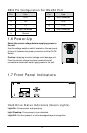
DB-9 Pin Configuration For RS-232 Port
Pin Use Pin Use
1 DCD 6 Not Connected
2 RX 7 RTS
3 TX 8 CTS
4 Not Connected 9 Not Connected
5 Ground
1.6 Power-Up
Select the correct voltage before supplying power to
the unit.
Use the voltage selector switch located on the rear panel
of the unit, between the power connector and the On/Off
Switch.
Caution: Applying incorrect voltage could damage unit.
Once the correct voltage has been selected and all
connections have been made, apply power to the unit.
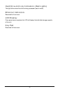
1.7 Front Panel Indicators
ACTIVITY
POWER 1 2 3 4 5 6 7 8
LINK READ WRITE 100
ETHERNET
HARD DRIVE STATUS
Disk Array
Hard Drive Status Indicators (Green Lights)
Light On: Drive present and operating.
Light Flashing: Drive present, error detected.
Light Off: No drive present, or drive damaged beyond recognition.