


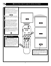
26
VOL
75 ⍀
VIDEO
L/
Mono
AUDIO
R
Monitor out
COMPONENT VIDEO INPUT
AV1 in
S-VIDEO
Y
Pb
Pr
75 ⍀
VIDEO
L/
Mono
AUDIO
R
Monitor out
COMPONENT VIDEO INPUT
AV1 in
S-VIDEO
Y
Pb
Pr
4
5
6
1
3
2
S-VIDEO
OUT
OUT
OUT
L
R
AUDIO
VIDEO
COMP VIDEO
Y
Pb
Pr
2
1
AV2 in
AV2 in
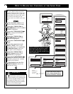
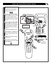
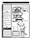
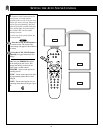
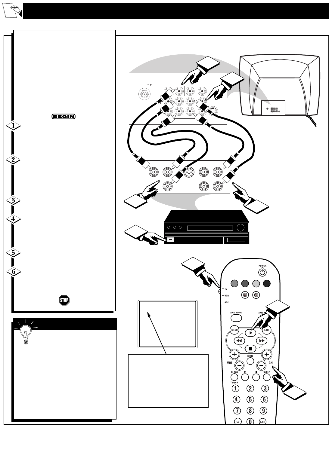
USING THE COMPONENT VIDEO INPUT JACKS
C
omponent Video inputs provide for
the highest possible color and pic-
ture resolution in the playback of digital
signal source material, such as with
DVD players. The color difference sig-
nals (Pb, Pr) and the luminance (Y) sig-
nal are connected and received sepa-
rately, which allows for improved color
bandwidth information (not possible
when using composite video or S-Video
connections).
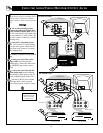
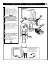
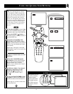
Connect the Component (Y, Pb,
Pr) Video OUT jacks from the DVD
player (or similar device) to the (Y, Pb,
Pr) in(put) jacks on the TV.
Connect the red and white AUDIO
CABLES to the Audio (left and right)
output jacks on the rear of the accesso-
ry device to the Audio (L and R) AV1
in(put) jacks on the TV.
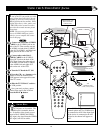
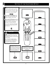
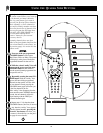
Turn the TV and the DVD (or dig-
ital accessory device) ON.
Press the CH + or – buttons to
scroll the available channels until CVI
appears in the upper left corner of the
TV screen.
Slide the TV/VCR/ACC Switch to
the ACC position.
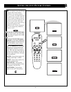
Insert a DVD disc into the DVD
player and press the PLAY
ᮣ button
on the remote.
Let's
Look
Inside!
AUDIO IN
(RED/WHITE)
COMPONENT
VIDEO CABLES
DVD, DBS OR SIMILAR ACCES-
SORY DEVICE EQUIPPED WITH
COMPONENT VIDEO JACKS.
BACK OF TV
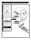
The description for the compo-
nent video connectors may differ
depending on the DVD player or acces-
sory digital source equipment used (for
example, Y, Pb, Pr; Y, B-Y, R-Y; Y, Cr,
Cb). Although abbreviations and terms
may vary, the letters b and r stand for
the blue and red color component signal
connectors, and Y indicates the lumi-
nance signal. Refer to your DVD or
digital accessory owner’s manual for
definitions and connection details.
SMART HELP
Note: CVI will appear as a
valid channel option only if a
digital device is connected to
the Component Video Input
Jacks. If no device is connect-
ed to the Component Video
Input Jacks, AV1 will appear.
CVI