


English
OSD (On Screen Display) Controls
23
En
PROGRAM TIMER
This sets the day and time at which the power will be
switched ON/OFF as well as the input mode.
Example: Setting so that the power will be switched
on at 8:30 A.M., Monday, displaying PC2 source, and
switched off at 10:30 A.M.
On “PROGRAM” of “TIMER” menu, select “ON”, then
press the MENU/SET button.
The “PROGRAM TIMER” screen appears.
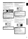
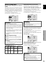
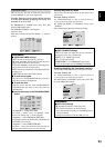
Adjust the items.
Each mode switches each time the ZOOM ם/מ button is
pressed.
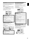
PROGRAM TIMER
DATE
MON
—
—
—
—
—
—
SEL.
ON
08 : 30
- - : - -
- - : - -
- - : - -
- - : - -
- - : - -
- - : - -
OFF
10 : 30
- - : - -
- - : - -
- - : - -
- - : - -
- - : - -
- - : - -
INPUT
PC2
—
—
—
—
—
—
FUNCTION
INVERSE
—
—
—
—
—
—
EXIT
RETURN
ZOOM
ADJ.
Information
Ⅵ PROGRAM TIMER settings
DATE: Set the day of the week (e.g. Sunday).
ON (hour, minutes): Set the time at which the power
will be turned on in the 24-hour format.
OFF (hour, minutes): Set the time at which the power
will be turned off in the 24-hour format.
INPUT: Set the input mode that will be displayed when
the timer is on.
FUNCTION: Set the LONG LIFE function.
Ⅵ To reset the program
Align the cursor with the DATE field that you wish to
reset, then press the CLEAR button.
Ⅵ To reset the data
Align the cursor with the field (ON/OFF/INPUT/
FUNCTION) that you wish to reset, then press the
CLEAR button.
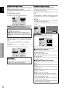
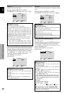
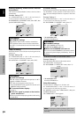
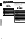
Ⅵ Special characters in the PROGRAM TIMER
screen
PROGRAM TIMER
DATE
MON
TUE
SAT
*FRI
—
SAT
*
SEL.
ON
08 : 30
- - : - -
08 : 30
08 : 30
- - : - -
08 : 30
15 : 30
OFF
10 : 30
18 : 15
12 : 15
10 : 00
- - : - -
12 : 15
16 : 00
INPUT
PC2
—
VIDEO1
COMP.1
—
VIDEO1
PC1
FUNCTION
INVERSE
—
WHITE
—
—
WHITE
—
EXIT
RETURN
ZOOM
ADJ.
• An asterisk “*” in the DATE field
An asterisk “*” means “every”. For example, “*FRI”
means every Friday and “*” means everyday.
• A hyphen “-” in the ON field or OFF field
If any hyphen remains in the ON field or OFF field, the
FUNCTION can not be set.
• A hyphen “-” in the FUNCTION field
A hyphen “-” means last mode (the mode that was last
selected at the time the power was switched off).
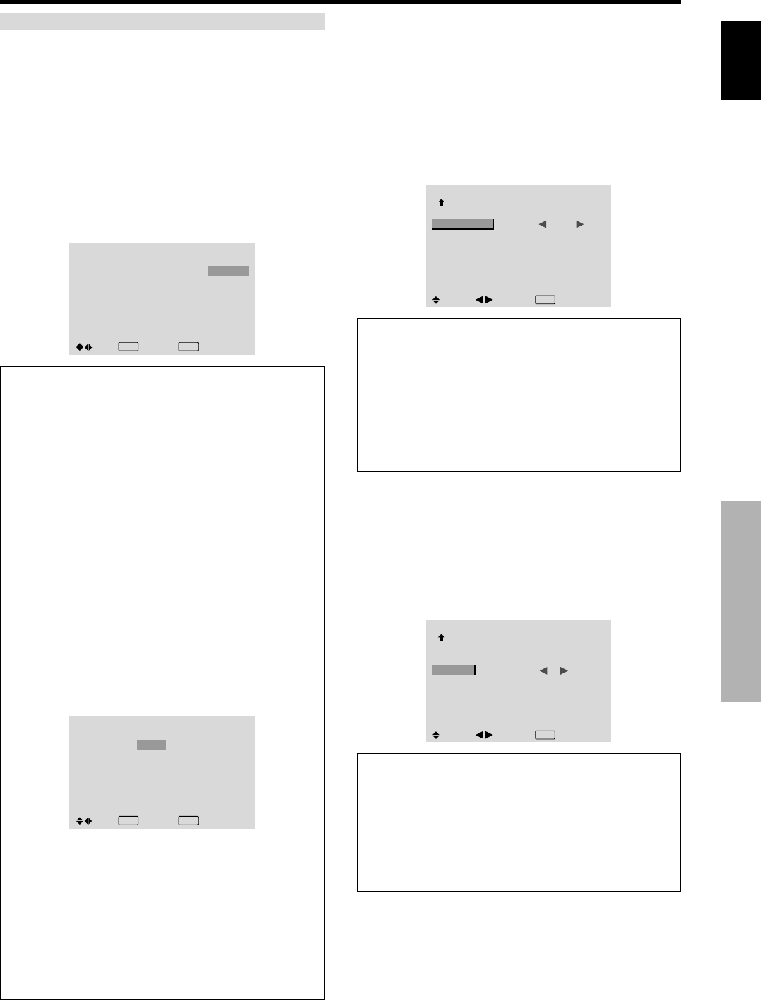
Setting the power on mode
This function sets the input mode at the time the power is
switched on.
Example: Setting “VIDEO2”
Set “ADVANCED OSD” to “ON” in the main menu (1/
2), then perform the following operations.
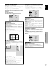
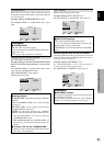
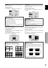
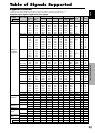
On “PWR. ON MODE” of “OPTION3” menu, select
“VIDEO2”.
The available inputs depend on the setting of input.
OPTION3
3 / 3
PREVIOUS PAGE
TIMER
PWR. ON MODE
KEY LOCK
IR REMOTE
LOOP OUT
ID NUMBER
VIDEO WALL
: VIDEO2
: OFF
: ON
: OFF
: ALL
SEL.
ADJ.
EXIT
RETURN
Information
Ⅵ PWR. ON MODE settings
LAST: Last mode (the input that was last selected at
the time the power was switched off).
VIDEO1, 2, 3: VIDEO input mode.
PC1, 2, 3: PC input mode.
COMPONENT1, 2: COMPONENT input mode.
Follow the procedure used for PROGRAM TIMER.
Enabling/disabling the front panel controls
This function enables/disables the front panel controls.
Example: Setting “ON”
Set “ADVANCED OSD” to “ON” in the main menu (1/
2), then perform the following operations.
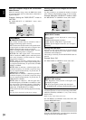
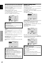
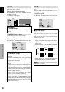
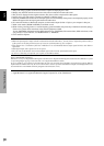
On “KEY LOCK” of “OPTION3” menu, select “ON”, then
press the MENU/SET button.
OPTION3
3 / 3
PREVIOUS PAGE
TIMER
PWR. ON MODE
KEY LOCK
IR REMOTE
LOOP OUT
ID NUMBER
VIDEO WALL
: LAST
: ON
: ON
: OFF
: ALL
SEL.
ADJ.
EXIT
RETURN
Information
Ⅵ KEY LOCK settings
ON: Disables the buttons on the front panel.
OFF: Enables the buttons on the front panel.
* Even when the KEY LOCK is set, the POWER switch
will not be locked.
* This becomes effective when the OSD goes out.