


EL640.480-AF1 VGA Operations Manual (020-0349-00A)
5
Specifications
Control Basics
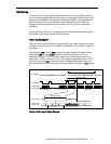
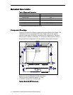
The EL panel is a matrix structure with column and row electrodes arranged in
an X-Y formation. Light is emitted when an AC voltage of sufficient amplitude
is applied at a row-column intersection. The display operation is based on the
symmetric, line at a time data addressing scheme. Required operating voltages
are provided by an integrated DC/DC converter.
Unless otherwise specified, performance characteristics are guaranteed when
measured at 25°C.
Power
The supply voltages are shown in Table 1. All internal high voltages are
generated from the display supply voltage (V
H
). The logic supply voltage (V
L
)
should be present whenever video input signals or V
H
is applied. The
minimum and maximum specifications in this manual should be met, without
exception, to ensure the long-term reliability of the display. Planar does not
recommend operation of the display outside these specifications.
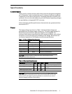
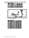
Table 1. DC Input Voltage Requirements.
AF1 Notes
V
L
+5 V ±5%
absolute max 7.0 V
V
H
+12 V ±10%
absolute max 15 V
I
L
, max 75 mA @ V
L
= +5 V
I
H
, max .7 A @ V
H
= +12 V
Ptyp, 120 Hz 4.5 W 3840 'E' characters
Pmax, 120 Hz 8.4 W 50/50 2x2 checkerboard
CAUTION: Absolute maximum ratings are those values beyond which
damage to the device may occur.
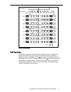
Table 2. Video Input Requirements.
Description Min Max Units Notes
Video logic high voltage 3.9 5.0 V All input thresholds are CMOS
Video logic low voltage 0 0.9 V
Video lines have 100 Ω series
resistors
Video logic input current –
±10
µA
CAUTION: There is no overcurrent protection on either the V
H
or V
L
inputs
to protect against catastrophic faults. Planar recommends the use of a series
fuse on the 12 volt supply. A general guideline is to rate the fuse at 1.8 to 2
times the display maximum current rating.