


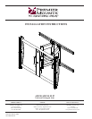
AM250
Installation Instructions Page 7
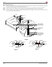
For ease of installation, it is recommended that two people perform the installation. One person should hold the mount
while the other person installs the lag bolt and washer. Making sure that the mount is level, the person not holding the
mount must mark and drill the second mounting hole and secure the second lag bolt and washer.
Mount Installation
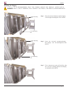
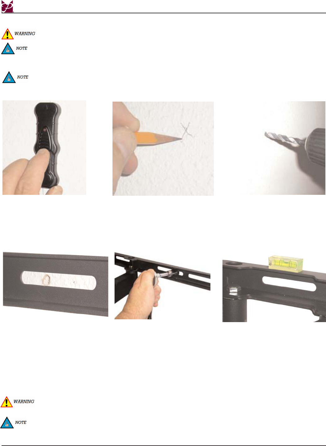
Step 1
Step 2
Step 3
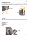
Step 4
Step 5
Step 6
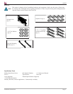
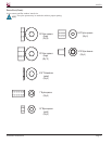
If the studs are 12” (304.8mm) apart, use three 3” (76.2mm) lag bolts for the top rail and three 3” (76.2mm) lag bolts for
the lower rail. If the studs are 16”(406.4mm), 18” (457.2mm) or 24” (609.6mm) apart, use two 3” lag bolts for the top
rail and two 3” lag bolts for the lower rail.
THE FOLLOWING STEPS SHOULD BE PERFORMED BY TWO PEOPLE.
Do NOT over-tighten lag bolts when attaching the mount to the wall. Improper installation may result in personal
injury or damage to property.
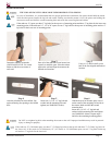
Determine where to mount the
AM250/AM250-FLIP. Use a stud
finder to find the exact center of
each stud.
Once all of the studs have been located, use
a pencil to mark the spots. Place the mount
against the wall and align the mount to the
marked stud locations.
Using a 1/4” drill bit, drill a pilot
hole at the first aligned and marked
location.
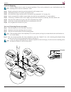
If the studs are 12” apart, use three 3” lag bolts for the top row of mounting points and three 3” lag bolts for the lower row
mounting points. If the studs are 16”, 18” or 24” apart, use two 3” lag bolts for the top row of mounting points and two 3”
lag bolts for the lower row of mounting points.
After the pilot hole has been drilled, line
up the mounting slot opening to the drilled
hole.
Insert one (1) 5/16" x 3" lag bolt and
washer into the mounting hole and
tighten (see WARNING: below).
With the help of an assistant, place a level
on the center of the mounting rail and level
the mount. Mark and drill the second
mounting hole.
Insert one (1) 5/16" x 3" lag bolt and
washer into the mounting hole and tighten
(see WARNING: below). Repeat steps 5
and 6 for the remaining mounting points.