


- 8 -
floor
floor
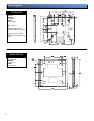
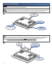
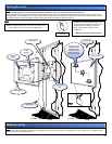
To determine the desired viewing height, use the center slot opening in the wall mount as a center reference for the plasma television when mounted. Once the height is determined,
use the bubble level to insure that the bracket is level. Next, using a pencil, mark the six (6) lag bolt slot openings on the mounting bracket. Before continuing, confirm the marks are
located on the center of the studs.
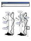
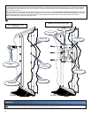
Drill 1/4" pilot holes on the six (6) markings on the wall. Raise the tilt back plate and have someone hold it in place (arrow side away from the wall and pointing up). Put the lag bolt
through the flat washers. Screw the lag bolt through the upper left slot opening into the 1/4" pilot hole. Confirm that the wall mount is still leveled and then screw a lag bolt to the upper
right side slot opening into the 1/4" pilot hole. Then install the remaining four lag bolts tightly into the wall studs in the lower left and right slot openings on the wall mount.
Make any lateral positioning if any then secure the lag bolts. See fig 4.
Wood studs behind
the wall structure
Drill gun with a 1/4"
drill bit
Wall structure
Marking on wall
Flat washers
5/16" Lag bolts
Access holes
Tilt back plate
Electrical
Step 4
All electrical wiring components should be installed at this time to ensure that the plasma display has enough power sources.
Note: Pre drill before the securing the
5/16" la
g
bolts.
Caution: Do not over tighten the 5/16" lag bolts
Center of
viewing marks