


PV500-9 04-2000 (1) Section 9
PVI FIREPOWER
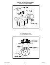
GAS BURNER
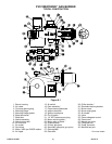
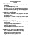
TYPICAL CONSTRUCTION
Figure 9-1
1. Burner housing 15. Air switch 29. Orifice location *
2. Air intake 16. Door assembly * 30. Electrode retaining bracket
3. Oil pump opening plug 17. Flame sensing electrode 31. Burner cover
4. Mounting flange 18. Ignition electrode 32. Burner sight glass
5. Mounting flange gasket 19. Ignition transformer 33. Air shutter
6. Blast tube screw 20. On-off switch * 34. Union
7. Blast tube 21. 1/4” NPT pressure port plug 35. Flame safeguard control
8. Nozzle assembly 22. Motor mounting plate * 36. Flame cone
9. Nozzle mount bolt 23. Motor relay or starter * 37. Manual gas valve
10. Air inlet cone 24. Pressure plate 38. Lifting eye bolt
11. Air screen 25. Primary gas ports 39. Power connector
12. Fan wheel 26. Secondary gas ports (gas spider) 40. Manifold test port
13. Motor, 3450 rpm CWSE rotation 27. Gas regulator
14. Air nipple 28. Gas valve
* On some models