


PV500-9 04-2000 (2) Section 9
POWER GAS BURNER START-UP
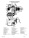
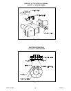
(Refer to Figure 9-1 to identify burner parts)
1. Remove the enclosure panel cover on the water heater
or boiler to expose the control circuit. Located on the
back side of this cover is a wiring diagram of the unit.
This diagram will show the controls used in our
circuitry.
2. Visually check to be sure all components are intact and
no damage has occurred during transit.
3. Check all connections within the control cabinet. A
loose connection on a component could cause
intermittent shutdowns.
4. Some burners will use direct spark ignition. They may
use a single gas pressure regulator and gas valve or
multiple valves and regulators. On a call for heat, the
motor starts, the gas primary control is energized, and
after a short delay (pre-purge), the gas valve(s) opens
and ignition should occur. Some burners have longer
pre-purge periods. On a call for heat, the control is
energized which starts the motor and begins a purge
sequence. On completion of the purge cycle, the gas
valve(s) opens and ignition occurs.
5. Remove flame safeguard control from its base. Check
connections in the control mounting base. Again, loose
connections can cause nuisance shutdowns. Also
check the time card or programmer, when applicable,
for good connection.
NOTE: Always secure gas lines and tag “Out of
Service” before servicing burner nozzle or electrodes.
6. Pull the nozzle assembly to check the flame and
ignition electrodes. This is done by first removing the
burner cover, exposing the nozzle assembly.
7. The L-Series burner must be removed from the heater
and the blast tube removed to access the electrodes.
The electrodes may be accessible by removing the
nozzle assembly on larger burners. Free the nozzle
assembly from the gas train by breaking the unions on
the gas lines. Some models will use an orifice that is
installed in these unions. Retain for re-use.
8. Next, remove the four bolts that hold the nozzle
assembly to the burner housing. Once the nozzle
assembly is free, pull it back slightly and remove the
wires going to the flame and ignition rod. The easiest
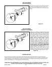
method of removing the nozzle assembly is to rotate it
90° upward and tilt slightly forward while working it
towards you (see Figure 9-2). Be careful not to damage
the electrodes.
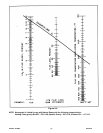
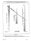
9. With the electrodes exposed, check them for the
proper settings as called for in Figure 9-3. Also check
for any hairline cracks in the insulators. Should
replacement of burner electrodes be required, certain
procedures must be followed. In all cases, removal of
the electrodes is accomplished by loosening the
electrode mounting bracket retaining screw. Draw the
electrodes out of the nozzle assembly through the
holes in the pressure plate.
10. Inspect the electrodes for cracked ceramics or loose
retaining studs that hold the wire within the ceramic.
Using supplied metric Allen wrench, loosen one or two
pressure plate retaining screws so that the plate rotates
freely on nozzle hub. Push plate towards the nozzle
assembly gas spider to ensure it remains fully back and
level. Do not re-tighten retaining screws at this time.
Select the proper pressure plate hole in which to place
each electrode and insert the electrode through the
hole, retaining stud end first. Place electrodes in the
electrode mounting bracket between the mount and the
retaining bracket.
11. Tighten electrode mounting bracket screw slightly until
electrode ceramics are seated firmly and completely in
mounting bracket without gaps between ceramics and
mounting bracket at the bearing faces.
NOTE: Electrodes may have a high temperature,
electrically insulating tape around them. The tape is
designed to cushion the ceramic insulators in the
mounting bracket, but is not absolutely necessary, and
may be removed if it interferes with the positioning of
the electrodes.
12. Ensure electrodes are loose enough to be rotated and
that they will slide back and forth in the mounting
bracket with firm finger pressure.
13. While ensuring the pressure plate is in the previously
described position, measure and set electrodes
according to Figure 9-3. After the gaps and settings are
complete, fully tighten the electrode mounting bracket
retaining screw. Do not overtighten or the insulation
may crack.
CAUTION: Electrodes may shift while tightening the
screw due to rotation of the upper electrode mounting
bracket. Holding down on this bracket while tightening
the screw will stop this from happening.
NOTE: The pressure plate may rotate on the nozzle hub
as the electrodes seek their position during the
tightening of the electrode mounting bracket retaining
screw. This is desirable to prevent the electrodes from
binding and not seating properly in the mounting
bracket. The electrode ceramics will crack, causing
ground faults in the circuit if this condition exists.
14. After complete mounting and positioning of the
electrodes is accomplished, rotate the pressure plate
so that no portion of the plate touches the electrode
ceramics at the holes the electrodes pass through in
the plate (ream holes slightly larger if needed to obtain