


14 REMOTE POWER CONTROL USER GUIDE
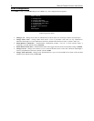
The Power Control Units RJ-45 control port uses the following signals:
EIA-232 RJ-45 PIN/SIGNAL DEFINITION
PIN EIA-232
SIGNAL
DIRECTION DESCRIPTION
1 DTR Output
+10V when activated by DCD; toggles upon logout for modem
disconnect.
2 GND ---- Signal Ground
3 RTS Output
+10V when powered is applied; not used as a handshake line
4 TX Output Transmit Data (data out)
5 RX Input Receive Data (data in)
6 N/C N/C No Connection
7 GND ----
Signal Ground
8 DCD Input
DCD into the Remote Power Control unit
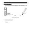
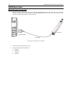
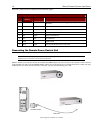
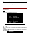
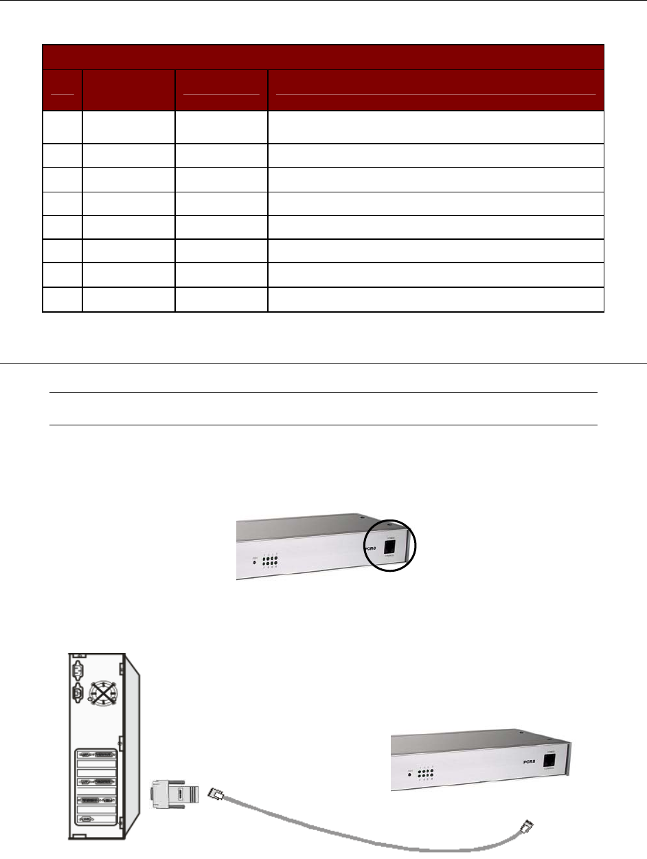
Connecting the Remote Power Control Unit
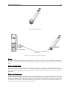
Note: On the PCR8, the RJ-45 port is located on the front panel of the unit. On both the PCS12 and PCS20,
the RJ-45 port is located on the end panels of the units.
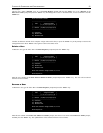
With the computer powered ON, connect the included APCSDB9F adapter into the serial port of the computer. Connect one end
of the included Cat5 cable to the APCSDB9F adapter and the other end to the RJ-45 port on the Remote Power Control unit. Plug
the Remote Power Control unit into the nearest wall outlet. The unit will automatically power ON.
PCR8 RJ-45 Port
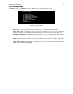
Connecting the Computer to a PCR8
Cat5e Cable
A
PCSDB9F Adapter
Local PC
PCR8 Unit